| | |
|  | | IMG-246024 |
|
| | Applies to all models Note!
Wait at least one minute before unplugging the connectors or removing other electrical equipment. |
|
|  | | IMG-291603 |
|
| | |
|  | | IMG-291604 |
|
| | |
|  | | IMG-303067 |
|
| | |
|  | | IMG-302788 |
|
|  | | IMG-302789 |
|
| | Illustrations A and B Detach the panel's lower, outer and inner ends from the lower panel and pull it from the clips at the sides. Repeat the operation on the other side.
|
|  | | IMG-302790 |
|
| | |
|  | | IMG-302983 |
|
| | |
|  | | IMG-303807 |
|
| | |
|  | | IMG-302984 |
|
|  | | IMG-302985 |
|
| | |
|  | | IMG-302986 |
|
|  | | IMG-302987 |
|
| | Applies to vehicles with electric boot lid opener Illustrations A and B |
|  | | IMG-303808 |
|
|  | | IMG-302988 |
|
| | Applies to all models Illustrations A and B Remove the lower panel by prying it off around the edge using a weatherstrip tool. Then carefully pull it off so that all the clips on the inside release. The cradle (1) in the centre of the inside of the panel is securely fastened. To release its catches it may be necessary to insert a screwdriver into the side of the panel, press the catches on both sides and remove the panel (see image B). If the car is equipped with a KV antenna, remove its connector.
|
|  | | IMG-303043 |
|
|  | | IMG-303064 |
|
| | |
|  | | IMG-303065 |
|
|  | | IMG-303066 |
|
| | |
|  | | IMG-281472 |
|
| | Note!
The roof panel is securely fastened. |
|
|  | | IMG-303068 |
|
| | |
|  | | IMG-303069 |
|
| | |
|  | | IMG-268017 |
|
| | |
|  | | IMG-268018 |
|
| | Fold the left-hand backrest forward. Remove the side cushion on the left by first pulling it backwards at the upper edge until the hooks (1) release. Then pull it inwards slightly until the hook (2) releases, and upwards until the locating pin (3) disengages from the mounting at the rear edge.
|
|  | | IMG-303083 |
|
| | |
|  | | IMG-303084 |
|
| | |
|  | | IMG-303085 |
|
| | Remove the C-pillar panel by carefully pulling it out at the lower edge so that the two retaining clips release. Pull it out at the upper edge until the last clip releases. Carefully unhook it from the roof panel.
|
|  | | IMG-303104 |
|
| | Take the angled end of a scriber and pull off the cover washers for the screws for the load securing eyelets. Remove the screws for the load securing eyelets and the screws at the front edge of the side panel.
|
|  | | IMG-303144 |
|
|  | | IMG-303145 |
|
| | |
|  | | IMG-303163 |
|
| | |
|  | | IMG-303164 |
|
| | |
|  | | IMG-303165 |
|
| | |
|  | | IMG-303166 |
|
| | |
|  | | IMG-303167 |
|
| | |
|  | | IMG-303168 |
|
| | |
|  | | IMG-303169 |
|
|  | | IMG-303170 |
|
|  | | IMG-303171 |
|
| | |
|  | | IMG-303172 |
|
|  | | IMG-303173 |
|
| | |
|  | | IMG-303174 |
|
| | Route the cable along the existing cable to the heating elements in the rear window towards the right-hand side of the boot lid. Route it along the right-hand side of the boot lid window up to the upper edge of it. Clamp it using a cable tie from the kit and pieces of butyl tape.
|
|  | | IMG-303175 |
|
| | |
|  | | IMG-303176 |
|
| | Press two cable ties with clips into the drilled holes. Press the cable into a piece of butyl tape above the right-hand hole for the panel's clips so that it does not get trapped when the panel is reinstalled. Tighten the cable with the clamps.
|
|  | | IMG-303177 |
|
| | Carefully pry off the left-hand side of the rubber grommet so that the catches release. Unhook the rubber grommet from the boot lid. Carry out the same with the end that is in the body.
|
|  | | IMG-303178 |
|
| | Note!
Reinforcements are located on the inside upper edge of the boot lid which can become blocked. Therefore, first insert the cable slightly to the left before inserting downwards. |
|
|  | | IMG-303265 |
|
| | |
|  | | IMG-303266 |
|
| | Insert the piece of wire through the boot lid's rubber grommet. Tape the connector and a piece of the cable at the wire. Lubricate the taped connector with low temperature grease.
Note!
The low temperature grease must not contain water. |
Remove the tape and wire spring.
|
|  | | IMG-303267 |
|
| | |
|  | | IMG-268048 |
|
|  | | IMG-268465 |
|
| | Illustrations A and B Take the receptacle housing section of the connector with the two metal strips from the kit. Carefully place the connector in the receptacle housing section with the round section (1) of the connector aligned in the corresponding cut-out (1) in the receptacle housing section. The upturned section (2) of the connector must also be aligned in the corresponding cut-out in the receptacle housing section.
Carefully place the other receptacle housing section on the connector. The upturned section (2) of the connector must be aligned in the corresponding cut-out in the receptacle housing section. Press the receptacle housings and connector together until the four catches engage.
Note!
The components are small and fragile, so take care when aligning the connector and receptacle housings in each other to avoid damage and resulting poor contact. |
|
|  | | IMG-303283 |
|
| | |
|  | | IMG-303284 |
|
|  | | IMG-303285 |
|
| | Illustrations A and B Route the cable harness to the left towards the D pillar. Route at the D pillar along the existing cable harness to the rear edge of the fuse holder. Secure it using seven cable ties along the existing cable harness.
Note!
Ensure that the cable does not chafe against the panel edge in the body where it exits the rubber grommet in its right-hand mounting. |
Insert a piece of wire under the rear edge on the load floor support along the thick cable harness and forward. Tape the connector and a piece of the cable on the routed cable harness (Image B) on the wire. Carefully pull the cable harness forward.
|
|  | | IMG-303286 |
|
| | |
|  | | IMG-303290 |
|
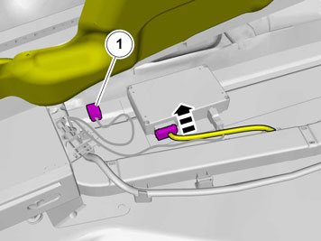
| | Measure the dimensions from the lugs in the floor and from the edge at the floor's embossing, and apply pieces of tape for marking the location of the ECU. Position the ECU along the markings and mark out the last short end.
|
|  | | IMG-307043 |
|
| | |
|  | | IMG-307044 |
|
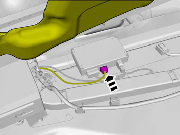
| | Note!
Ensure to turn the ECU correctly. |
|
|  | | IMG-254321 |
|
| | |
|  | | IMG-285834 |
|
| | |
|  | | IMG-241925 |
|
| | |
|  | | IMG-307045 |
|
| | |
|  | | IMG-307046 |
|
| | |
|  | | IMG-307047 |
|
| | |
|  | | IMG-303291 |
|
| | |
|  | | IMG-339078 |
|
|  | | IMG-339082 |
|
| | Applies to vehicles with factory fitted RTI Illustrations A and B Connect the existing power supply cable. Locate the cable (1) from the RTI screen, it is in foam rubber in the connection to the MMM module. Connect the cable.
|
|  | | IMG-297972 |
|
| | Applies to vehicles without RTI |
|  | | IMG-298585 |
|
| | |
|  | | IMG-282523 |
|
| | |
|  | | IMG-282524 |
|
| | |
|  | | IMG-282526 |
|
|  | | IMG-282525 |
|
| | |
|  | | IMG-282527 |
|
| | |
|  | | IMG-303365 |
|
| | |
|  | | IMG-282532 |
|
| | |
|  | | IMG-282530 |
|
| | |
|  | | IMG-282528 |
|
| | |
|  | | IMG-282533 |
|
| | |
|  | | IMG-282543 |
|
| | |
|  | | IMG-282544 |
|
| | |
|  | | IMG-296139 |
|
| | Applies to vehicles with an automatic gearbox |
|  | | IMG-296140 |
|
| | |
|  | | IMG-282545 |
|
| | |
|  | | IMG-282546 |
|
|  | | IMG-282547 |
|
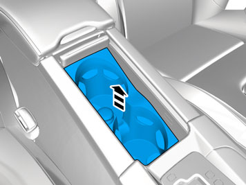
| | Illustrations A and B Carefully pry off the centre console's panel starting at both sides at the rear edge. It is secured by two clips along the long sides and four hooks around the gear lever's panel. Lift it up slightly and make sure that all cables are free from the gear lever carrier and components in the tunnel console, and lift it out.
|
|  | | IMG-286854 |
|
| | |
|  | | IMG-287243 |
|
| | |
|  | | IMG-303384 |
|
| | |
|  | | IMG-303385 |
|
| | |
|  | | IMG-303804 |
|
| | |
|  | | IMG-303805 |
|
| | |
|  | | IMG-283145 |
|
|  | | IMG-275076 |
|
| | |
|  | | IMG-303809 |
|
| | |
|  | | IMG-303810 |
|
| | |
|  | | IMG-303811 |
|
| | |
|  | | IMG-303823 |
|
|  | | IMG-303826 |
|
| | Cable harness marked B and C in the kit are only used for vehicles without installed display. Routing cable harness B Illustrations A and B Pull out the B post panel at the lower edge until the two clips release. Continue to route the cable harness inside the B pillar panel and forwards in the car. Route the cable harness along the left-hand side, in front of the floor and insulation panels, up to the front edge of the door opening.
|
|  | | IMG-303829 |
|
|  | | IMG-303834 |
|
| | Applies to left-hand drive vehicles Routing cable harness B, continued Illustrations A and B Route the cable harness in the mat joint under the driver's seat towards the tunnel console and inside the mat. Route it through the tunnel console, in front of the air ducts and out on the other side. Use a piece of wire to route the cables through, if necessary.
|
|  | | IMG-303835 |
|
| | Applies to right-hand drive vehicles Routing cable harness B, continued |
|  | | IMG-303837 |
|
| | |
|  | | IMG-303838 |
|
|  | | IMG-303841 |
|
| | Illustrations A and B Place the two large connectors for the cable harness where the two 32-pin connectors were previously disconnected from each other. Route the thin ground cable (1) in the mat joint in the same direction as cable harness B to the control module.
Note!
Ensure that the cables do not come into contact with moving parts in the tunnel console and that they are not at risk of being cut. |
Only applies to left-hand drive vehicles |
|  | | IMG-303846 |
|
| | Routing the ground cable in cable harness C, continued Route the ground cable the same way as cable harness B, up to the control module. Press the B pillar panel into place again.
Note!
Ensure that the ground cable is routed so that it is not at risk of being trapped or cut by sharp edges or similar. |
|
|  | | IMG-303849 |
|
| | |
|  | | IMG-303855 |
|
| | Take special tool, part no. 9512637 and carefully press into the hole above the connector in terminal 15 to release the cable terminal's primary lock. Pull out the existing cable, insulate the cable terminal and tape the cable at the cable harness to the connector.
|
|  | | IMG-303859 |
|
| | |
|  | | IMG-303860 |
|
| | |
|  | | IMG-303861 |
|
| | Clamp the ground cable using cable ties at the rear edge of the cable duct. Press two cable ties with edge clips in the bracket legs for the electric parking brake, or media player, and clamp the cable to these.
|
|  | | IMG-303863 |
|
| | |
|  | | IMG-303865 |
|
| | Note!
The ground lead must only be taped at the rear crossmember, it must not be secured by the thick cable harness. |
|
|  | | IMG-303867 |
|
| | |
|  | | IMG-303868 |
|
|  | | IMG-303869 |
|
| | Applies to left-hand drive vehicles Illustrations A and B Routing cable harness B/cable harness C Insert the wire into the centre console, up towards the compartment above the air outlet and out through the hole on the right-hand side in the compartment where the display is to be positioned. Tape the connector and a piece of the cable at the wire spring. Route the cable(s) on the right-hand side in the compartment where the media player was located. Pull the cable(s) forward.
|
|  | | IMG-303883 |
|
|  | | IMG-303884 |
|
| | Applies to right-hand drive vehicles Illustrations A and B Routing cable harness B/cable harness C Insert the wire into the centre console, up towards the compartment above the air outlet and out through the hole on the left-hand side in the compartment where the display is to be positioned. Tape the connector and a piece of the cable at the wire spring. Route the cable(s) on the left-hand side in the compartment where the media player was located. Pull the cable(s) forward.
|
|  | | IMG-339237 |
|
| | Applies to all models Note!
Ensure that the two locating pins (small image) exit their holes and are not bent when the panel is bent backwards. If necessary, press the tunnel and centre console backwards further. |
|
|  | | IMG-303886 |
|
| | |
|  | | IMG-303887 |
|
| | Note!
Do not damage the display and panel. |
|
|  | | IMG-303888 |
|
| | |
|  | | IMG-303889 |
|
| | |
|  | | IMG-303890 |
|
| | |
|  | | IMG-303891 |
|
| | |
|  | | IMG-303892 |
|
|  | | IMG-303893 |
|
| | |
|  | | IMG-303894 |
|
| | |
|  | | IMG-303895 |
|
| | |
|  | | IMG-303896 |
|
| | |
|  | | IMG-303897 |
|
| | |
|  | | IMG-282557 |
|
|  | | IMG-282558 |
|
| | Illustrations A and B Take the panel with CCM and insert the cables in the tunnel console. Place it at the upper edge and secure it with clips at the rear edge. Secure the panel in the centre console. Make sure that all clips engage.
|
|  | | IMG-282559 |
|
| | |
|  | | IMG-303943 |
|
| | Connect the connector (1) that was disconnected from the tunnel console's left-hand side to the corresponding connector (2) in the routed adapter cable. Attach clips to the cable harness in the tunnel console. Connect the remaining connectors to each other. Wrap foam tape around the loose connectors and position them inside the mats so that they do not move. Secure the long cables at the existing cable harness using cable ties from the kit.
|
|  | | IMG-303965 |
|
| | |
|  | | IMG-303966 |
|
| | |
|  | | IMG-282566 |
|
| | |
|  | | IMG-282564 |
|
| | |
|  | | IMG-282565 |
|
| | |
|  | | IMG-303983 |
|
|  | | IMG-303984 |
|
| | Illustrations A and B Replacement of the panel for the air vent |
|  | | IMG-303985 |
|
| | |
|  | | IMG-303987 |
|
| | |
|  | | IMG-303988 |
|
| | |
|  | | IMG-282568 |
|
| | |
|  | | IMG-282569 |
|
| | |
|  | | IMG-282567 |
|
| | |
|  | | IMG-255787 |
|
| | |
|  | | IMG-304003 |
|
| | |
|  | | IMG-304005 |
|
| | |
|  | | IMG-304007 |
|
| | |
|  | | IMG-304008 |
|
| | |
|  | | IMG-304009 |
|
| | |
|  | | IMG-268064 |
|
| | |
|  | | IMG-268106 |
|
| | |
|  | | IMG-268107 |
|
| | |
|  | | IMG-304010 |
|
| | |
|  | | IMG-304011 |
|
| | |
|  | | IMG-304012 |
|
| | |
|  | | IMG-304013 |
|
| | Install new clips in the lower panel. Pull the cables for the lighting and contact for the door opener out through the hole in the panel. If the car is equipped with a KV antenna, connect its connector. secure the panel and ensure that all clips engage.
|
|  | | IMG-304014 |
|
|  | | IMG-304015 |
|
| | Applies to vehicles with electric opener for boot lid |
|  | | IMG-304016 |
|
| | |
|  | | IMG-304017 |
|
|  | | IMG-304018 |
|
| | |
|  | | IMG-304019 |
|
| | Check that all clips are intact and properly positioned. Replace any broken clips. Reinstall the upper panel by first pressing the upper edge and then the sides at the same time as aligning the lower panel.
Note!
Make sure that the clips align with their holes. |
|
|  | | IMG-304020 |
|
| | |
|  | | IMG-291605 |
|
| | |
|  | | IMG-291606 |
|
| | |
|  | | IMG-336901 |
|
| | |
|  | | IMG-336904 |
|
| | Warning!
When the ignition is to be switched on for the first time after the battery has been disconnected, this must be done whilst by standing outside the vehicle, stretching your arm in and avoiding the working area for the airbags. |
|
|  | | IMG-242268 |
|
| | |
|  | | IMG-336903 |
|
| | Perform the function test as follows. Engage reverse gear. Activate the screen for RTI. Wait for the message "Update Environment" to appear on the screen. Follow the on-screen instructions Switch off the ignition for at least 10 seconds. Turn the ignition on Activate the screen for RTI Check that the support lines appear on the screen and that these react to steering wheel movements.
|
| | | IMG-242268 |
|
| | |