| | |
|  | | IMG-363036 |
|
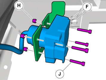
| | Color symbols Used for focused part, the part that you are to do something with. Used as extra colors when you need to show or highlight additional parts. Used for fasteners to be removed/installed. May be screws, clips, connectors, etc. Used when part is not removed completely from the vehicle but is only hung/suspended off to the side. Used for standard tools and special tools. Used as background color on vehicle parts.
|
|  | | IMG-245980 |
|
| | Note!
Wait at least three minutes before disassembling the connectors or removing other electrical equipment. |
|
|  | | IMG-346921 |
|
| | |
|  | | IMG-346811 |
|
| | |
|  | | IMG-360187 |
|
| | |
|  | | IMG-362267 |
|
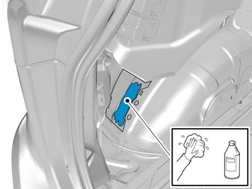
| | Installing TRM Use: Isopropanol, part number 1161721 |
|  | | IMG-356179 |
|
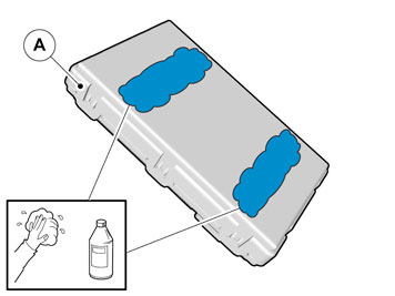
| | Use:Isopropanol, part number 1161721 |
|  | | IMG-356181 |
|
| | |
|  | | IMG-222282 |
|
| | |
|  | | IMG-241925 |
|
| | |
|  | | IMG-356351 |
|
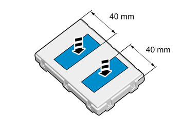
| | When installing Velcro tape the surface must maintain a temperature of at least +20 ° C (68°F). |
|  | | IMG-356352 |
|
| | |
|  | | IMG-362292 |
|
| | |
|  | | IMG-362298 |
|
| | Applies to cars model year from 2013- |
|  | | IMG-362296 |
|
| | |
|  | | IMG-347027 |
|
| | Applies to cars model year up to and incl. -2012 |
|  | | IMG-362307 |
|
| | |
|  | | IMG-360183 |
|
| | |
|  | | IMG-362318 |
|
| | |
|  | | IMG-362319 |
|
| | |
|  | | IMG-359922 |
|
| | |
|  | | IMG-360189 |
|
| | |
|  | | IMG-285841 |
|
| | |
|  | | IMG-368513 |
|
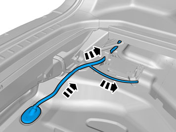
| | Installing trailer hitch cable harness |
|  | | IMG-368519 |
|
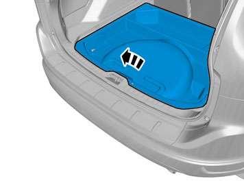
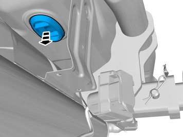
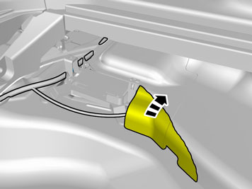
| | Remove the rubber grommet in the floor and place it to one side, it shall not be used again. |
|  | | IMG-368522 |
|
| | Note!
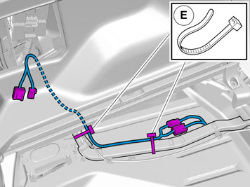
Install the rubber grommet so that the cable points to the left on the inside. |
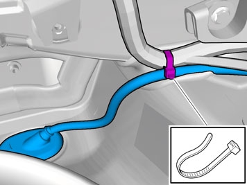
Insert the cable with the connector into the hole in the spare wheel well and install the rubber grommet. Adapt the length of the cable from the connector to the rubber grommet so that the cable is not too slack beneath the car.
|
|  | | IMG-366117 |
|
| | |
|  | | IMG-368533 |
|
| | |
|  | | IMG-366072 |
|
| | |
|  | | IMG-366316 |
|
| | |
|  | | IMG-366140 |
|
| | Applies to vehicles with DVD reader |
|  | | IMG-366142 |
|
| | |
|  | | IMG-366146 |
|
| | |
|  | | IMG-366124 |
|
| | |
|  | | IMG-366276 |
|
| | Applies to vehicles with chassis number up to and incl. -175378 |
|  | | IMG-366471 |
|
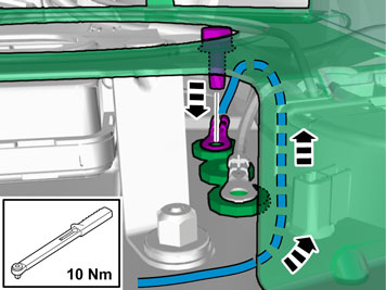
| | Note!
Connect to an available ground terminal, in one of the three existing. |
|
|  | | IMG-366473 |
|
| | Applies to vehicles with chassis number up to and incl. from 175379- |
|  | | IMG-366131 |
|
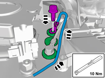
| | Note!
Connect to an available ground terminal, in one of the three existing. |
|
| | |
|  | | IMG-242268 |
|
| | |
|  | | IMG-249951 |
|
| | Checking the trailer connector 7-pin connection Brake lamp / Left-hand indicator lamp Ground Spare (Brake lamp, Electric brakes) Brake lamp / Right-hand indicator lamp Charging Position lamps Spare (Reversing lamp)
The cable for pin 3 for 7-pin connection is blue (BL). It is taped on the cable harness approx. 1 meter from the trailer socket. 4-pin connection Brake lamp / Right-hand indicator lamp Brake lamp / Left-hand indicator lamp Position lamps Ground
|