| | |
| | Read through all of the instructions before starting installation. Notifications and warning texts are for your safety and to minimise the risk of something breaking during installation. Ensure that all tools stated in the instructions are available before starting installation. Certain steps in the instructions are only presented in the form of images. Explanatory text is also given for more complicated steps. In the event of any problems with the instructions or the accessory, contact your local Volvo dealer.
|
| | |
|  | | IMG-363036 |
|
| | Used for focused component, the component with which you will do something. Used as extra colors when you need to show or differentiate additional parts. Used for attachments that are to be removed/installed. May be screws, clips, connectors, etc. Used when the component is not fully removed from the vehicle but only hung to the side. Used for standard tools and special tools. Used as background color for vehicle components.
|
| | |
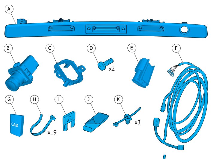
| | There may be parts in the accessories kit that are not needed for this installation. |
|  | | IMG-332193 |
|
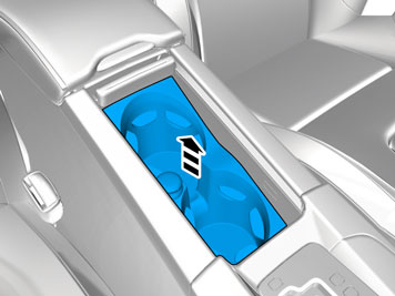
| | Set the ignition key to position 0. |
| | |
|  | | IMG-345728 |
|
| | |
|  | | IMG-345734 |
|
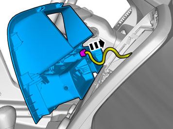
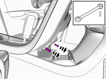
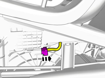
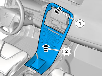
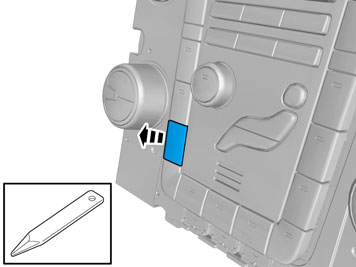
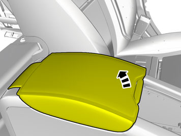
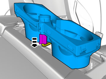
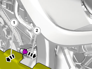
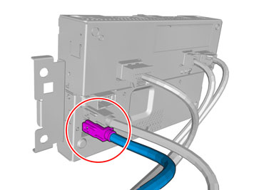
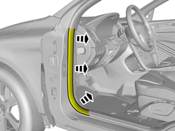
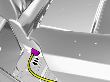
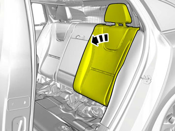
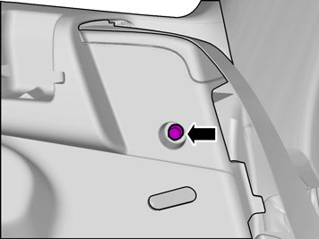
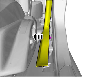
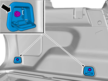
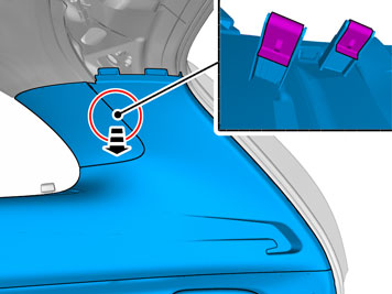
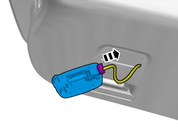
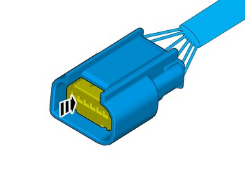
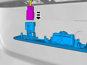
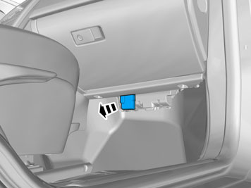
| | Disconnect the connector. |
|  | | IMG-345736 |
|
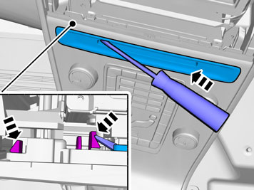
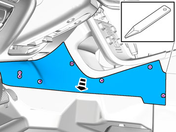
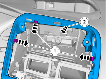
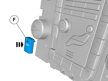
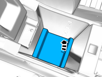
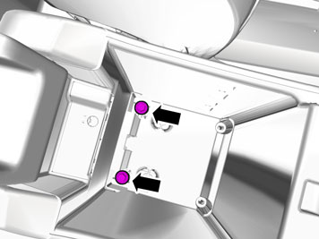
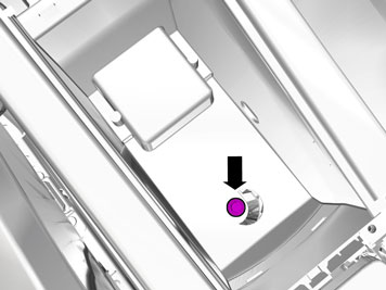
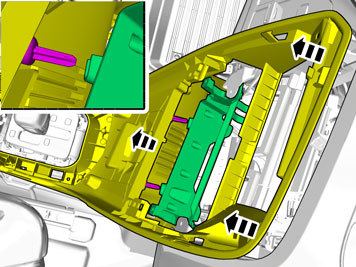
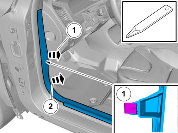
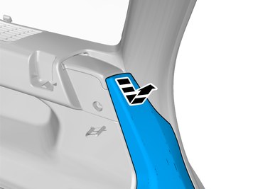
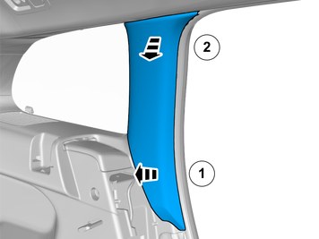
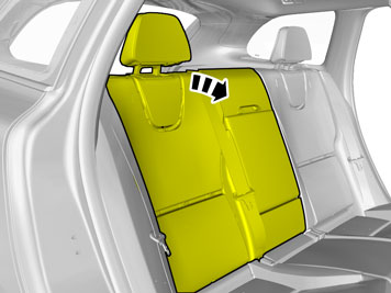
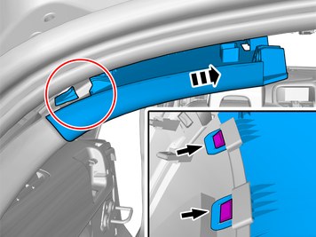
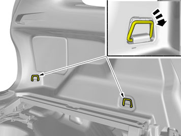
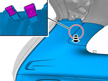
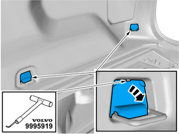
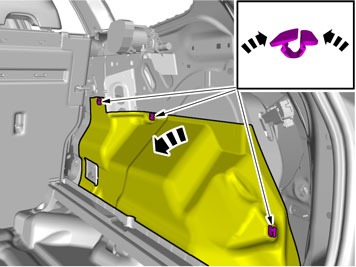
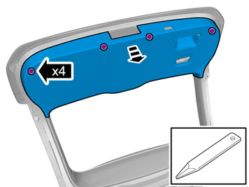
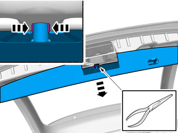
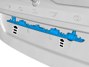
| | Note!
Perform the procedure one side at a time. |
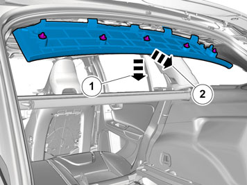
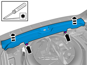
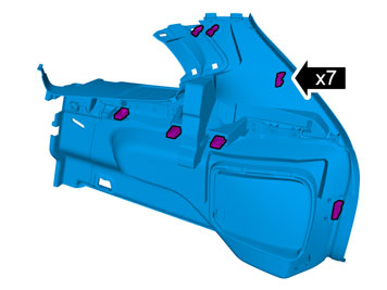
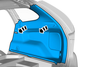
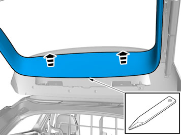
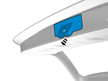
Release the catch. |
|  | | IMG-345737 |
|
| | |
|  | | IMG-345744 |
|
| | |
|  | | IMG-345282 |
|
| | |
|  | | IMG-340598 |
|
| | |
|  | | IMG-340599 |
|
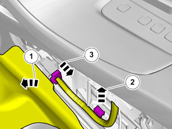
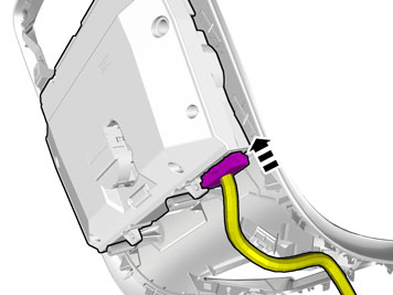
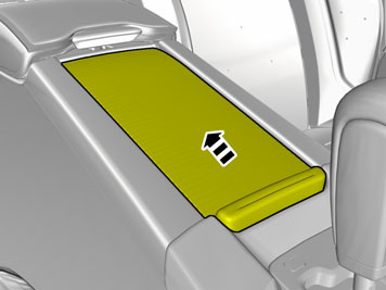
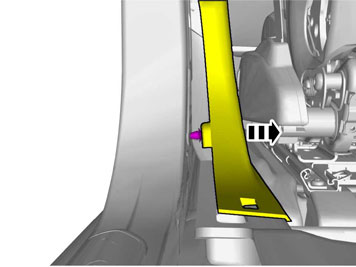
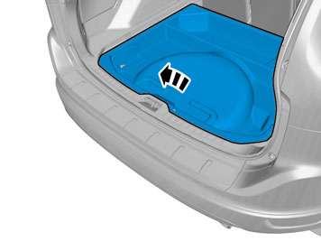
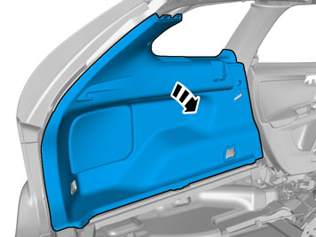
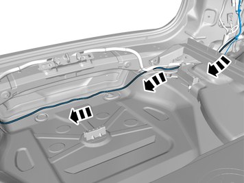
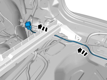
| | Fold the carpet aside. Unhook the clip(s). Disconnect the connector.
|
|  | | IMG-340600 |
|
| | |
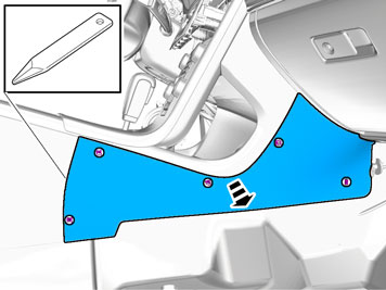
| | Vehicles with the 4C system. |
|  | | IMG-340601 |
|
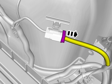
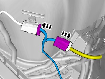
| | Disconnect the connector. |
| | Cars with automatic transmissions |
|  | | IMG-345283 |
|
| | |
|  | | IMG-293007 |
|
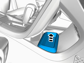
| | Release the shift-lock function. Move the gear lever to D.
|
| | |
|  | | IMG-293009 |
|
| | |
|  | | IMG-293010 |
|
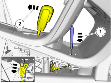
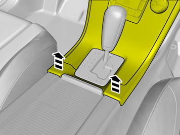
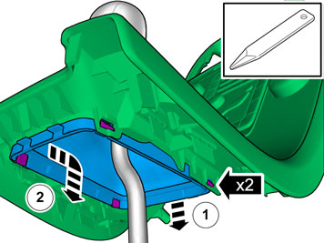
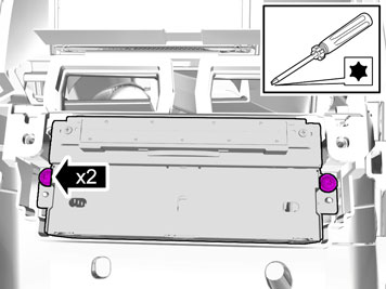
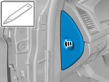
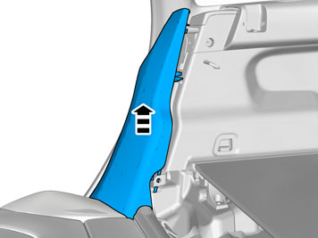
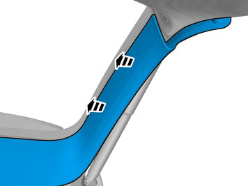
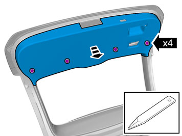
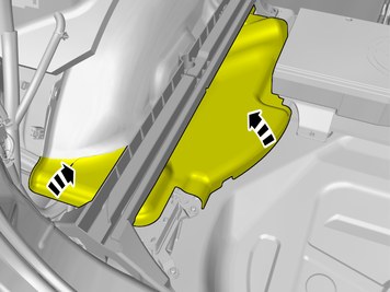
| | Release the catches. Detach the panel.
|
|  | | IMG-345754 |
|
| | |
|  | | IMG-345292 |
|
| | |
|  | | IMG-345290 |
|
| | |
| | Vehicles with the 4C system. |
|  | | IMG-345291 |
|
| | |
| | |
|  | | IMG-340604 |
|
| | Disconnect the connector. |
|  | | IMG-340605 |
|
| | |
|  | | IMG-345762 |
|
| | |
|  | | IMG-380815 |
|
| | |
| | |
|  | | IMG-399720 |
|
| | |
| | |
|  | | IMG-345765 |
|
| | |
| | | IMG-340605 |
|
| | |
|  | | IMG-340622 |
|
| | |
| | |
| | Vehicles with Sensus Connect |
|  | | IMG-345767 |
|
| | |
|  | | IMG-345766 |
|
| | |
|  | | IMG-399566 |
|
| | Disconnect the connector, if applicable. |
|  | | IMG-399598 |
|
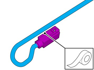
| | The connector is not to be used. Attach the connector to the wiring harness. Use: , Electrical tape
|
|  | | IMG-380933 |
|
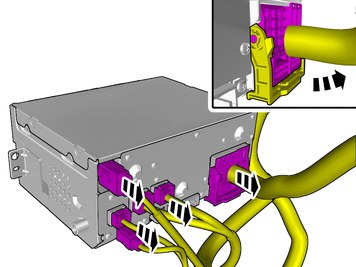
| | Note!
The number of connectors may vary depending on the vehicle's equipment level. |
Disconnect the connectors. |
| | Vehicles without Sensus Connect |
|  | | IMG-341780 |
|
| | |
|  | | IMG-341781 |
|
| | |
|  | | IMG-341782 |
|
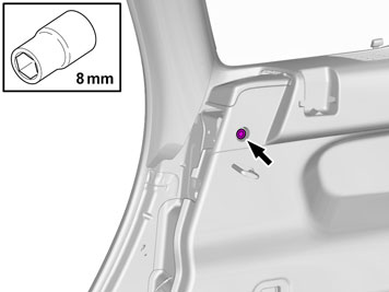
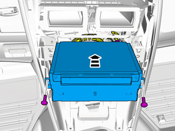
| | Remove the screws.
Tightening torque: M8
, 24 Nm
|
|  | | IMG-341773 |
|
| | |
|  | | IMG-341776 |
|
| | |
|  | | IMG-341777 |
|
| | Disconnect the connector. |
|  | | IMG-346026 |
|
| | Remove the screw.
Tightening torque: M8
, 24 Nm
|
|  | | IMG-341771 |
|
| | Fold the carpet aside. Remove the screw.
Tightening torque: M8
, 24 Nm
|
|  | | IMG-341746 |
|
| | Fold the carpet aside. Remove the screw.
Tightening torque: M8
, 24 Nm
|
|  | | IMG-345770 |
|
| | |
|  | | IMG-346281 |
|
| | |
|  | | IMG-345774 |
|
| | |
|  | | IMG-345773 |
|
| | |
|  | | IMG-352166 |
|
| | Disconnect the connector, if applicable. |
| | | IMG-399598 |
|
| | The connector is not to be used. Attach the connector to the wiring harness. Use: , Electrical tape
|
|  | | IMG-346175 |
|
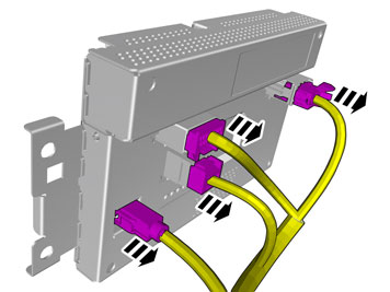
| | Note!
The number of connectors may vary depending on the vehicle's equipment level. |
Disconnect the connectors. |
| | |
|  | | IMG-346687 |
|
| | |
|  | | IMG-346689 |
|
| | |
|  | | IMG-346676 |
|
| | Caution!
The front and upper sill panel must be removed and installed as one unit. |
|
|  | | IMG-346681 |
|
| | |
|  | | IMG-346677 |
|
| | |
|  | | IMG-346682 |
|
| | |
|  | | IMG-399651 |
|
| | Repeat on the other side. |
|  | | IMG-341902 |
|
| | Disconnect the connector, if applicable. Repeat on the other side. |
|  | | IMG-399653 |
|
| | |
|  | | IMG-343672 |
|
| | |
|  | | IMG-399654 |
|
| | |
|  | | IMG-399655 |
|
| | |
|  | | IMG-399656 |
|
| | |
|  | | IMG-347040 |
|
| | |
|  | | IMG-399657 |
|
| | |
|  | | IMG-346701 |
|
| | |
|  | | IMG-346797 |
|
| | |
|  | | IMG-346796 |
|
| | |
|  | | IMG-377298 |
|
| | |
|  | | IMG-377299 |
|
| | |
|  | | IMG-377300 |
|
| | |
|  | | IMG-377302 |
|
| | |
|  | | IMG-377309 |
|
| | |
|  | | IMG-377320 |
|
| | |
|  | | IMG-346792 |
|
| | |
|  | | IMG-343420 |
|
| | |
|  | | IMG-399658 |
|
| | Detach the panel. Repeat on the other side. |
|  | | IMG-399659 |
|
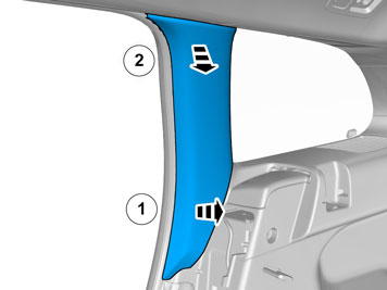
| | Release the catches. Remove the panel. Repeat on the other side. |
|  | | IMG-346921 |
|
| | |
|  | | IMG-346811 |
|
| | |
|  | | IMG-346861 |
|
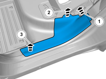
| | Remove the screws. Remove the panel.
|
|  | | IMG-347011 |
|
| | |
|  | | IMG-347026 |
|
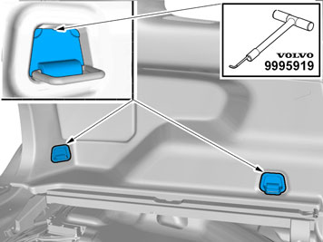
| |
Use special tool: T9995919, PULLER (SEAL-PINION,CAM-CRANKSHAFT)B200-6304
|
|  | | IMG-347331 |
|
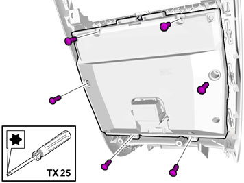
| | Remove the screws.
Tightening torque: M8
, 24 Nm
|
|  | | IMG-347051 |
|
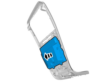
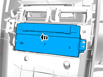
| | Note!
The graphic shows the back of the component before removal. |
|
|  | | IMG-399680 |
|
| | |
|  | | IMG-347036 |
|
| | |
|  | | IMG-307608 |
|
| | |
|  | | IMG-307609 |
|
| |
Use special tool: T9995919, PULLER (SEAL-PINION,CAM-CRANKSHAFT)B200-6304
|
| | | IMG-307609 |
|
| | Remove the screws.
Tightening torque: M8
, 24 Nm
|
|  | | IMG-377350 |
|
| | |
|  | | IMG-377352 |
|
| | Remove the panel. Disconnect the connector, if applicable. |
|  | | IMG-308085 |
|
| | |
|  | | IMG-308086 |
|
| | Remove the clips. Fold the insulation aside. |
|  | | IMG-346866 |
|
| | Remove the screw. Repeat on the other side. |
|  | | IMG-346872 |
|
| | Detach the panel. Repeat on the other side. |
|  | | IMG-346876 |
|
| | Detach the panel. Repeat on the other side. |
|  | | IMG-346882 |
|
| | |
|  | | IMG-346886 |
|
| | |
|  | | IMG-346887 |
|
| | |
|  | | IMG-346891 |
|
| | |
|  | | IMG-346892 |
|
| | Disconnect the connector. |
| | Vehicles with power liftgate |
|  | | IMG-347056 |
|
| | |
|  | | IMG-347057 |
|
| | Disconnect the connector. |
| | |
|  | | IMG-346916 |
|
| | |
|  | | IMG-346917 |
|
| | |
|  | | IMG-346918 |
|
| | |
|  | | IMG-347071 |
|
| | |
|  | | IMG-347096 |
|
| | |
|  | | IMG-399843 |
|
| | Disconnect the connector. |
|  | | IMG-399988 |
|
| | |
|  | | IMG-399989 |
|
| | |
| | |
|  | | IMG-382372 |
|
| |
Use special tool: T9512932, Tension spring
|
|  | | IMG-399925 |
|
| | Install the cable. Use: , Electrical tape
|
|  | | IMG-399910 |
|
| | |
|  | | IMG-399915 |
|
| | |
|  | | IMG-399917 |
|
| | Pull the wiring through. Remove the Special Tool. |
|  | | IMG-401046 |
|
| | |
|  | | IMG-399835 |
|
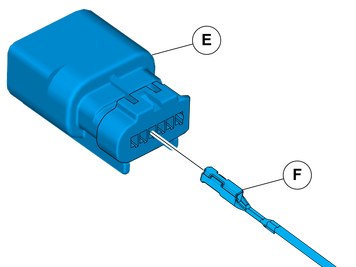
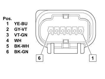
| | Connect the cable harness terminals in the connector as follows. |
|  | | IMG-401095 |
|
| | Depress the secondary lock. |
|  | | IMG-399927 |
|
| | |
|  | | IMG-399850 |
|
| | |
|  | | IMG-399840 |
|
| | |
|  | | IMG-399842 |
|
| | |
|  | | IMG-399844 |
|
| | |
| | | IMG-347071 |
|
| | Install the nuts
Tightening torque: Exterior handle to tailgate/luggage compartment lid
, 5 Nm
|
|  | | IMG-399955 |
|
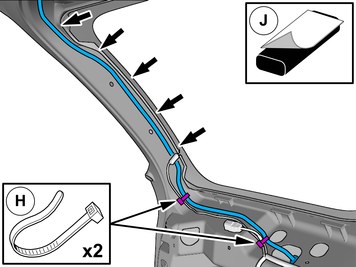
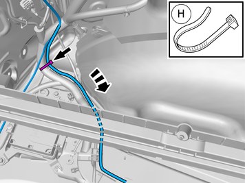
| | Install the cable. Use: , Strip clamp
Use: , Butyl tape
|
|  | | IMG-348136 |
|
| | |
|  | | IMG-348137 |
|
| | |
|  | | IMG-348138 |
|
| | |
|  | | IMG-399962 |
|
| | Install the cable. Use: , Strip clamp
Use: , Butyl tape
|
|  | | IMG-399985 |
|
| | Adjust the position of the wiring harness. |
|  | | IMG-347257 |
|
| | |
|  | | IMG-399992 |
|
| | |
|  | | IMG-399997 |
|
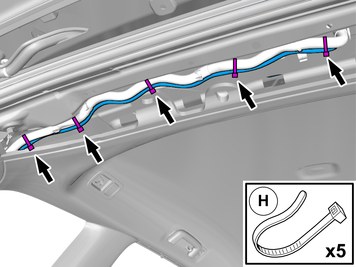
| | Install the cable. Use a cable tie |
|  | | IMG-399999 |
|
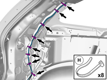
| | Install the cable. Use a cable tie |
|  | | IMG-399998 |
|
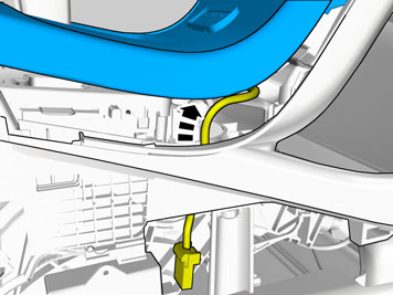
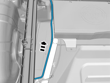
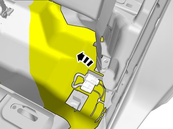
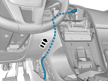
| | Position/route the cable harness as illustrated. |
|  | | IMG-400036 |
|
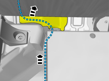
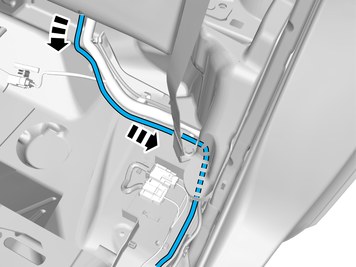
| | Position/route the cable harness as illustrated. |
|  | | IMG-400038 |
|
| | Disconnect the connector. |
|  | | IMG-400042 |
|
| | |
|  | | IMG-400065 |
|
| | Fold the insulation aside. |
|  | | IMG-400077 |
|
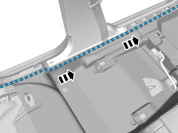
| | Position/route the cable harness as illustrated. |
|  | | IMG-400080 |
|
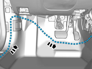
| | Position/route the cable harness as illustrated. |
|  | | IMG-400092 |
|
| | Fold the insulation aside. Route the cable harness to the existing cable harness. |
|  | | IMG-400100 |
|
| | Fold the insulation aside. |
|  | | IMG-400101 |
|
| | Route the cable harness to the existing cable harness. |
|  | | IMG-400105 |
|
| | Position/route the cable harness as illustrated. |
|  | | IMG-400106 |
|
| | Position/route the cable harness as illustrated. |
| | Vehicles without Sensus Connect |
|  | | IMG-400111 |
|
| | Position/route the cable harness as illustrated. |
|  | | IMG-348748 |
|
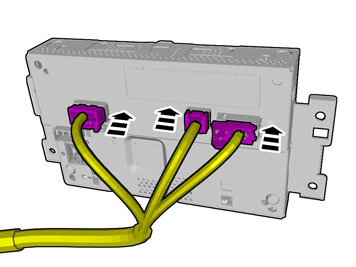
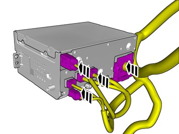
| | Note!
The number of connectors, cables and cable ties can vary depending on the vehicle's equipment level. |
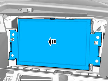
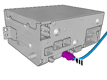
Connect the connectors. |
| | Vehicles with 5 inch ICM-display |
|  | | IMG-352266 |
|
| | |
| | Vehicles with 7 inch display |
|  | | IMG-352267 |
|
| | |
|  | | IMG-400114 |
|
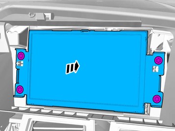
| | Reinstall the removed part. |
| | Vehicles with Sensus Connect |
|  | | IMG-400119 |
|
| | |
|  | | IMG-384899 |
|
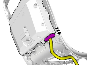
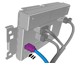
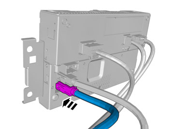
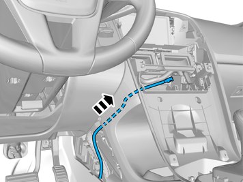
| | Connect the prerouted cable. |
|  | | IMG-380943 |
|
| | |
|  | | IMG-346121 |
|
| | Reinstall the removed part. |
| | |
|  | | IMG-381919 |
|
| | |
|  | | IMG-400174 |
|
| | |
|  | | IMG-400000 |
|
| | Reinstall the removed parts in reverse order. |
|  | | IMG-242268 |
|
| | Download software (application) for the accessory's function according to the service information in VIDA. See VIDA or the accessories catalogue for software part number. |
|  | | IMG-400005 |
|
| | Calibrate according to: DIAGNOSTICS/VEHICLE COMMUNICATION/Advanced/PAC/Service calibration, parking camera |