2012 R.H.D

安裝說明

Installation instructions, accessories
Volvo Car Corporation Gothenburg, Sweden
XC60 2012
XC60 (-17) 2012 R.H.D

Instruction NoVersionPart. No.Click to download PDF-version of this Installation Instruction
313306721.131339994, 31332429
Parking assistance, camera, front blind view


Equipment
IMG-242205
A0000162
IMG-239664
IMG-300203
IMG-327738
IMG-239667

IMG-345727


INTRODUCTION

  • Read through all of the instructions before starting installation.

  • Notifications and warning texts are for your safety and to minimise the risk of something breaking during installation.

  • Ensure that all tools stated in the instructions are available before starting installation.

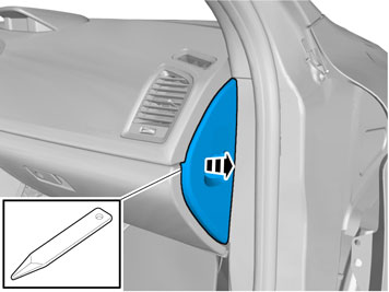
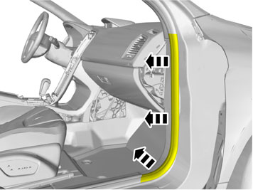
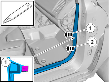
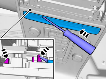
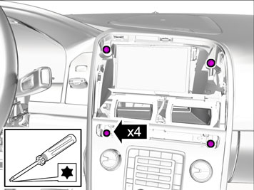
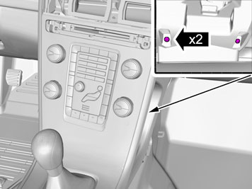
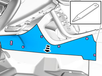
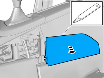
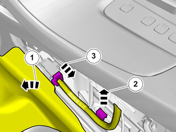
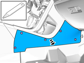
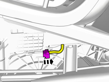
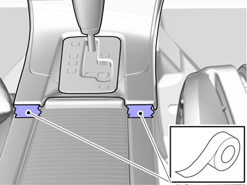
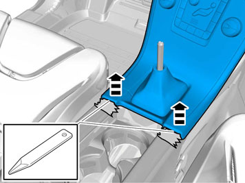
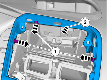
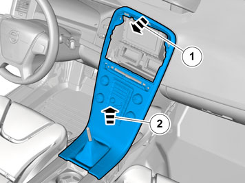
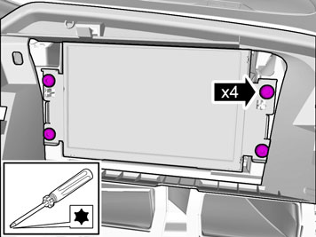
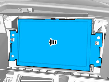
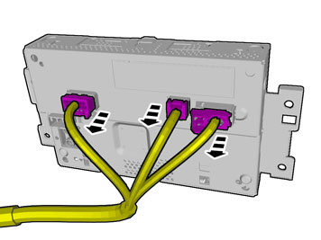
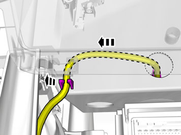
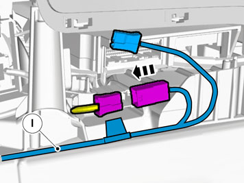
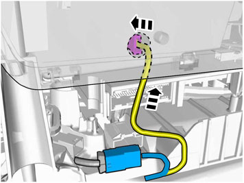
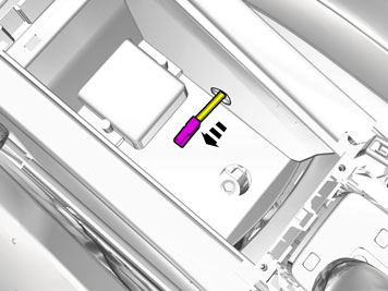
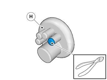
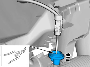
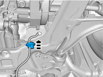
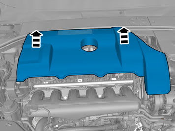
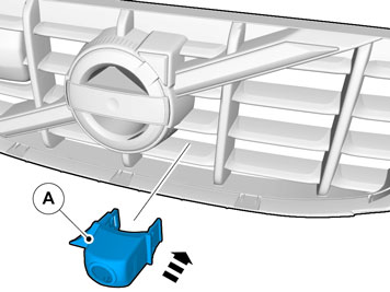
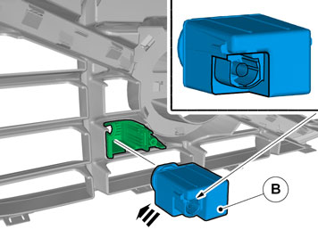
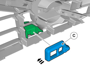
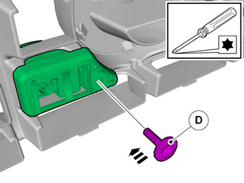
  • Certain steps in the instructions are only presented in the form of images. Explanatory text is also given for more complicated steps.

  • In the event of any problems with the instructions or the accessory, contact your local Volvo dealer.


Note!

Some steps in these installation instructions are presented with illustration only.


1
IMG-332193
 

  • Set the ignition key to position 0.


Note!

Wait at least one minute before unplugging the connectors or removing other electrical equipment.


2
IMG-308353
 

  • Disconnect any connector(s).

3
IMG-308354
 

  • Remove the sealing strip.

4
IMG-286863


Caution!

Remove the front and upper sill panel as one unit.


5
IMG-308355
 

6
IMG-308356
 

7
IMG-344451
 

8
IMG-345728
 

  • Remove the panel.

9
IMG-345734
 

  • Unplug the connector.

10
IMG-345736
 

  • Release the hooks.


Note!

One side at a time.


11
IMG-345737
 

12
IMG-345744
 

  • Remove the screws.

13
IMG-345745
 

  • Remove the screws.

14
IMG-340598
 

  • Remove the panel.

15
IMG-345746
 

  • Remove the panel.

16
IMG-340599
 

  • Fold the carpet to one side.

  • Unhook the clip(s).

  • Unplug the connector.

17
IMG-340600
 

  • Remove the panel.

18
IMG-340601
 

Applies to vehicles with dynamic suspension

  • Unplug the connector.

19
IMG-340596
 

Applies to vehicles with an automatic transmission

20
IMG-293007
 

  • Release the shift-lock function.

  • Move the gear selector to position "D".

21
IMG-345747
 

Applies to vehicles with manual transmissions

  • Release the catch that is located inside the boot. Pull the locking sleeve and boot downward. Ensure that the boot does not come loose from the catch.

22
IMG-345749
 

  • Release the catch.

23
IMG-345751
 

24
IMG-340602
 

Applies to all vehicles

  • Use suitable tape to protect the components.

25
IMG-345753
 

26
IMG-293010
 

27
IMG-345754
 

28
IMG-340604
 

  • Unplug the connector.

29
IMG-345756
 

  • Remove the screws.

30
IMG-345762
 

31
IMG-345763
 

32
IMG-345764
 

33
IMG-345765
 

34
IMG-345756
 

  • Reinstall the screws.

35
IMG-340622
 

  • Plug in the connector.

36
IMG-345767
 

  • Remove the screws.

37
IMG-345766
 

38
IMG-345769
 

  • Disconnect the connectors. The number of connectors, cables and cable ties can vary depending on the vehicle's equipment level.

39
IMG-341780
 

40
IMG-341781
 

41
IMG-341782
 

  • Remove the screws.

    Tightening torque: 24 Nm

42
IMG-341773
 

43
IMG-341776
 

44
IMG-341777
 

  • Disconnect any connector(s).

45
IMG-346026
 

  • Remove the screw.

    Tightening torque: 24 Nm

46
IMG-341771
 

  • Fold the carpet to one side.

  • Remove the screw.

    Tightening torque: 24 Nm

47
IMG-341746
 

  • Fold the carpet to one side.

  • Remove the screw.

    Tightening torque: 24 Nm

48
IMG-345770
 

49
IMG-346281
 

50
IMG-345774
 

  • Remove the screws.

51
IMG-345773
 

52
IMG-345776
 

  • Disconnect the connectors. The number of connectors, cables and cable ties can vary depending on the vehicle's equipment level.

53
IMG-345777
 

54
IMG-345778
 

55
IMG-345779
 

56
IMG-345846
 

57
IMG-345847
 

58
IMG-345848
 

  • Tear off the excess foam tape.

59
IMG-345849
 

60
IMG-345850
 

61
IMG-345851
 

  • Ensure that no part of the cable harness is trapped.

62
IMG-345901
 

  • Ensure that the cable is routed so that it does not come into contact with any moving parts.

63
IMG-345902
 

64
IMG-345906
 

65
IMG-345911
 

66
IMG-345916
 

  • Locate the rubber grommet under the thick insulation mat and press it outwards.


Note!

Position a long tool sleeve between the body and insulation to facilitate cable routing later on.


67
IMG-345917
 

  • Insert the connector through the hole for the rubber grommet.

68
IMG-345861
 

  • Connect the connectors. The number of connectors can vary depending on the vehicle's equipment level.

69
IMG-345862
 

70
IMG-345767
 

  • Reinstall the screws.

71
IMG-345863
 

  • Plug in the connectors.

72
IMG-345864
 

73
IMG-345774
 

  • Reinstall the screws.

74
IMG-345865
 

75
IMG-345866
 

  • Use suitable tape to protect the components.

76
IMG-345867
 

77
IMG-345871
 

78
IMG-345872
 

79
IMG-345873
 

  • Remove the component carefully.

80
IMG-345874
 

81
IMG-345875
 

82
IMG-345876
 

83
IMG-346042
 

84
IMG-345919
 

85
IMG-345877
 

  • Remove the clips.

  • Remove the screws.

86
IMG-345878
 

87
IMG-345920
 

  • Locate the hole for the rubber grommet on the cowl panel.


Note!

On certain models this may be covered by the heat insulation.


88
IMG-345921
 

  • Pull through the cable.

89
IMG-345881
 

90
IMG-345922


Note!

Do not expand the hole more than is necessary to get the switch through, the rubber lead-in can easily split.


  • Use: Low temperature grease 1161427

91
IMG-345923
 

92
IMG-273585
 

Vehicles with diesel engines or 6-cylinder petrol engines

93
IMG-340532
 

Applies to all models

  • Remove the nuts.

94
IMG-340579
 

95
IMG-345924
 

96
IMG-345926


Note!

Do not tighten the clamp yet.


Caution!

Make sure that the cable is positioned so that it is not damaged by heat or wear.


97
IMG-345927
 

98
IMG-307911
 

99
IMG-345928
 

  • Route the cable to the existing cable harness.

100
IMG-345929
 

101
IMG-340782
 

102
IMG-345930
 

  • Tighten the clamp securely.

103
IMG-347781
 

  • Remove the lens cover for the camera.

104
IMG-347786
 

  • Install the O-ring.

105
IMG-345891
 

106
IMG-345892
 

  • Check that the camera is installed the correct way at installation.

107
IMG-345893
 

108
IMG-345894
 

109
IMG-345931
 

110
IMG-345896
 

111
IMG-345932
 

  • Insert the cable in the passenger compartment, adjust the cable excess out in the engine compartment and press the rubber grommet into place. Place any excess under the floor carpet.


Caution!

Tighten the clamps securely.


  • Reinstall the detached components in reverse order.

112
IMG-242268
 

  • Download software (application) for the accessory's function according to service information in VIDA. See VIDA or accessories catalogue for article number on software.