| | |
|  | | IMG-332193 |
|
| | Applies to all models Note!
Wait at least one minute before unplugging the connectors or removing other electrical equipment. |
|
|  | | IMG-291603 |
|
| | |
|  | | IMG-291604 |
|
| | |
|  | | IMG-303067 |
|
| | |
|  | | IMG-302788 |
|
|  | | IMG-302789 |
|
| | Illustrations A and B Detach the panel's lower, outer and inner ends from the lower panel, and pull it from the clip at the sides. Repeat the operation on the other side.
|
|  | | IMG-302790 |
|
| | |
|  | | IMG-302983 |
|
| | |
|  | | IMG-303807 |
|
| | |
|  | | IMG-302984 |
|
|  | | IMG-302985 |
|
| | |
|  | | IMG-302986 |
|
|  | | IMG-302987 |
|
| | Applies to cars with electric boot lid opener Illustrations A and B |
|  | | IMG-329745 |
|
|  | | IMG-329746 |
|
| | Applies to all models Illustrations A and B Remove the lower panel by first prying loose the four clips at the bottom. Then pull the panel off carefully, insert a pair of flat-nosed pliers, press the locking pin's hooks together and pull the locking pin out. Continue to pull the panel down carefully until the four upper clips release.
|
|  | | IMG-303043 |
|
|  | | IMG-303064 |
|
| | |
|  | | IMG-303065 |
|
|  | | IMG-303066 |
|
| | Illustration A Illustration B |
|  | | IMG-281472 |
|
| | Note!
The roof panel is securely fastened. |
|
|  | | IMG-303068 |
|
| | |
|  | | IMG-303069 |
|
| | |
|  | | IMG-328943 |
|
| | |
|  | | IMG-328944 |
|
| | Applies to cars with electrically heated seat cushions |
|  | | IMG-268017 |
|
| | |
|  | | IMG-268018 |
|
| | Fold the left-hand backrest forward. Remove the side cushion on the left by first pulling it backwards at the upper edge until the hooks (1) release. Then pull it inwards slightly until the hook (2) releases, and upwards until the locating pin (3) disengages from the mounting at the rear edge.
|
|  | | IMG-303083 |
|
| | |
|  | | IMG-303084 |
|
| | |
|  | | IMG-303085 |
|
| | Remove the C-pillar panel by carefully pulling it out at the lower edge so that the two retaining clips release. Pull it out at the upper edge until the last clip releases. Carefully unhook it from the roof panel.
|
|  | | IMG-303104 |
|
| | Take the angled end of a scriber and pull off the cover washers for the screws for the load securing eyelets. Remove the screws for the load securing eyelets and the screws at the front edge of the side panel.
|
|  | | IMG-303144 |
|
|  | | IMG-303145 |
|
| | |
|  | | IMG-328958 |
|
| | |
|  | | IMG-330068 |
|
| | |
|  | | IMG-328959 |
|
| | |
|  | | IMG-328960 |
|
|  | | IMG-303170 |
|
|  | | IMG-303171 |
|
| | |
|  | | IMG-303172 |
|
|  | | IMG-303173 |
|
| | |
|  | | IMG-303174 |
|
| | Route the cable along the existing cable to the heating elements in the rear window towards the right-hand side of the boot lid. Route it along the right-hand side of the boot lid window up to the upper edge of it. clamp it using a cable tie from the kit and pieces of butyl tape.
|
|  | | IMG-303175 |
|
| | |
|  | | IMG-303176 |
|
| | Press two cable ties with clips into the drilled holes. Press the cable into a piece of butyl tape above the right-hand hole for the panel's clips so that it does not get trapped when the panel is reinstalled. Tighten the cable with the clamps.
|
|  | | IMG-303177 |
|
| | Carefully pry off the left-hand side of the rubber grommet so that the catches release. Unhook the rubber grommet from the boot lid. Carry out the same with the end that is in the body.
|
|  | | IMG-303178 |
|
| | Note!
Reinforcements are located on the inside upper edge of the boot lid which can become blocked. Therefore, first insert the cable slightly to the left before inserting downwards. |
|
|  | | IMG-303265 |
|
| | |
|  | | IMG-303266 |
|
| | Insert the piece of wire through the boot lid's rubber grommet. Tape the connector and a piece of the cable at the wire. Lubricate the taped connector with low temperature grease.
Note!
The low temperature grease must not contain water. |
|
|  | | IMG-303267 |
|
| | |
|  | | IMG-328963 |
|
|  | | IMG-328964 |
|
| | Illustrations A and B Take the receptacle housing with catch for the camera cable's contact from the kit. Press the receptacle housing onto the connector until a click is heard. Press the catch securely into the receptacle housing.
Note!
The components are small and fragile, so take care when aligning the connector and receptacle housing with catch into each other to avoid damage and resulting poor contact. |
|
|  | | IMG-303283 |
|
| | |
|  | | IMG-303284 |
|
|  | | IMG-328965 |
|
| | Illustrations A and B Route the cable harness to the left towards the D pillar. Route at the D pillar along the existing cable harness to the rear edge of the fuse holder. Secure it using seven cable ties along the existing cable harness.
Note!
Ensure that the cable does not chafe against the panel edge in the body where it exits the rubber grommet in its right-hand mounting. |
Insert a piece of wire under the rear edge on the load floor support along the thick cable harness and forward. Tape the connector and a piece of the cable on the routed cable harness (Image B) on the wire. Carefully pull the cable harness forward.
|
|  | | IMG-328966 |
|
| | |
|  | | IMG-298164 |
|
| | |
|  | | IMG-298165 |
|
| | |
|  | | IMG-297972 |
|
| | |
|  | | IMG-298585 |
|
| | |
|  | | IMG-282523 |
|
| | |
|  | | IMG-282524 |
|
| | |
|  | | IMG-282526 |
|
|  | | IMG-282525 |
|
| | |
|  | | IMG-282527 |
|
| | |
|  | | IMG-303365 |
|
| | |
|  | | IMG-282532 |
|
| | |
|  | | IMG-282530 |
|
| | |
|  | | IMG-282528 |
|
| | |
|  | | IMG-282533 |
|
| | |
|  | | IMG-282543 |
|
| | |
|  | | IMG-282544 |
|
| | |
|  | | IMG-296139 |
|
| | Applies to cars with automatic transmission |
|  | | IMG-296140 |
|
| | |
|  | | IMG-282545 |
|
| | |
|  | | IMG-282546 |
|
|  | | IMG-282547 |
|
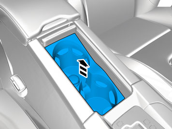
| | Illustrations A and B Carefully pry off the centre console's panel starting at both sides at the rear edge. It is secured by two clips along the long sides and four hooks around the gear lever's panel. Lift it up slightly and make sure that all cables are free from the gear lever carrier and components in the tunnel console, and lift it out.
|
|  | | IMG-286854 |
|
|  | | IMG-287243 |
|
| | |
|  | | IMG-303384 |
|
| | |
|  | | IMG-303385 |
|
| | |
|  | | IMG-303804 |
|
| | |
|  | | IMG-303805 |
|
| | |
|  | | IMG-283145 |
|
|  | | IMG-275076 |
|
| | |
|  | | IMG-303809 |
|
| | |
|  | | IMG-303810 |
|
| | |
|  | | IMG-303811 |
|
| | |
|  | | IMG-303812 |
|
| | For all cars with display Note!
Ensure that the two locating pins (small image) exit their holes and are not bent when the panel is bent backwards. If necessary, press the tunnel and centre console backwards further. |
|
|  | | IMG-303813 |
|
| | |
|  | | IMG-303815 |
|
| | Note!
The cables may be short. |
|
|  | | IMG-352251 |
|
| | |
|  | | IMG-329230 |
|
|  | | IMG-329253 |
|
| | Applies to all models Illustration A Illustration B Pull out the B post panel at the lower edge until the two clips release. Continue to route the cable harness in front of the B-pillar panel and to the front of the car to the joint between the front and rear floor mat.
|
|  | | IMG-329254 |
|
|  | | IMG-303834 |
|
| | Applies to left-hand drive cars Illustrations A and B Note!
Check that the correct connector is positioned under the seat respectively tunnel console. |
Routing cable harness B Take cable harness B from the kit and route it into the mat joint under the left-hand seat towards the tunnel console and in front of the mat. Leave some cable, approximately 350 mm (13 3/4 ") in length, outside the mat joint, so that it can later be connected to the control module that is to be positioned there. Route it through the tunnel console, in front of the air ducts and out on the other side. If necessary, use a piece of wire to route the cables through.
|
|  | | IMG-329255 |
|
| | Applies to right-hand drive cars Note!
Check that the correct connector is positioned under the seat respectively tunnel console. |
Routing cable harness B Route the cable harness into the mat joint under the driver's seat towards the tunnel console, in front of the mat and out onto the floor. Leave some cable, approximately 350 mm (13 3/4 ") in length, outside the mat joint, so that it can later be connected to the control module that is to be positioned there.
|
|  | | IMG-329256 |
|
| | Applies to all cars that do not have a pre-mounted display. |
|  | | IMG-329257 |
|
|  | | IMG-329258 |
|
| | Illustration A Tilt the left-hand seat back. Place the two large connectors for the cable harness where the two 32-pin connectors were previously disconnected from each other. Route the thinner ground leads (1) into the mat joint in the same direction as cable harness B, along the member for the front seat mounting where the control module will be installed later on. Pull up the shorter ground lead (2) from the mat joint so that approximately 350 mm 13 3/4 " protrudes from the mat joint. Continue to route the longer of the ground leads the same way as cable harness A backwards towards the rear crossmember.
Note!
Ensure that the cables do not come into contact with moving parts in the tunnel console and that they are not at risk of being cut. |
Illustration B Only applies to left-hand drive vehicles. Route through the thicker cable (3) to the display through the tunnel console in front of the air ducts and out the other side. Use a wire to route the cables through, if necessary.
|
|  | | IMG-329259 |
|
| | Routing the ground cable in cable harness C, continued route the ground lead the same way as cable harness A towards the rear crossmember. Press the B pillar panel into place again.
Note!
Ensure that the ground cable is routed so that it is not at risk of being trapped or cut by sharp edges or similar. |
|
|  | | IMG-329260 |
|
| | Clamp the ground cable using cable ties at the rear edge of the cable duct. Press two cable ties with edge clips in the bracket legs for the electric parking brake, or media player, and clamp the cable to these.
|
|  | | IMG-303863 |
|
| | |
|  | | IMG-303865 |
|
| | Note!
The ground lead must only be taped at the rear crossmember, it must not be secured by the thick cable harness. |
|
|  | | IMG-303867 |
|
| | |
|  | | IMG-329261 |
|
| | |
|  | | A3700183 |
|
|  | | A3700174 |
|
| | Illustration A Splicing the ground lead in cable harness C Splicing with insulated damp-sealed crimping sleeve Colour | Cable area, mm² | Stripping length mm | Green/White | 0.3 - 0.5 | 5 | Red | 0.5 - 1.0 | 6 | Blue | 1.0 - 2.5 | 7 | Yellow | 4.0 - 6.0 | 7 |
Illustration B |
| | Pressing the sleeve Illustration A Insert the crimping sleeve in the press tool P/N 9512785. Select the socket as per colour coding. Clamp the pliers together slightly, but only so that the crimping sleeve remains in the pliers. Insert the cable in the crimping sleeve until it reaches the stop.
Note!
Make sure that the cable insulation does not come into the press area of the sleeve or that the stripped part or the cable extends outside of the sleeve. |
Illustrations B and C Press the legs of the pliers completely together to ensure a proper splice. The pliers will then release automatically. With your hand, check that the crimping sleeve is securely in place.
|
|  | | D3701792 |
|
|  | | A3700190 |
|
| | Heating the crimping sleeve Illustrations A and B Place a suitable shield behind the cables to be crimped to prevent thermal stress to the surrounding area. Warm the sleeve with a hot air gun, P/N 9512777, and suitable nozzle. It is extremely important that the crimping sleeve be securely crimped around the cable. You should be able to see that a little bit of glue has been forced out around the cable. (Illustration B).
|
|  | | IMG-329262 |
|
| | |
|  | | IMG-329263 |
|
| | Applies to all cars that do not have a pre-mounted display. |
|  | | IMG-329264 |
|
| | Take special tool, part no. 9512637 and carefully press into the hole above the cable terminal in position 1 to release the catch. Pull out the existing black cable.
|
|  | | IMG-329265 |
|
| | |
|  | | IMG-329266 |
|
| | |
|  | | IMG-329267 |
|
| | |
|  | | IMG-329272 |
|
| | |
|  | | IMG-329273 |
|
| | |
|  | | IMG-329274 |
|
| | |
|  | | IMG-329275 |
|
| | Note!
Ensure that the cables are correctly positioned and bent at the connectors. |
|
|  | | IMG-329276 |
|
| | |
|  | | IMG-298584 |
|
| | |
|  | | IMG-298586 |
|
| | |
|  | | IMG-303868 |
|
|  | | IMG-303869 |
|
| | Applies to left-hand drive cars Illustrations A and B Routing cable harness B/cable harness C Insert the wire into the centre console, up towards the compartment above the air outlet and out through the hole on the right-hand side in the compartment where the display is to be positioned. Tape the connector and a piece of the cable(s) at the spring wire. Route the cable(s) on the right-hand side in the compartment where the media player was located. Pull the cable(s) forward.
|
|  | | IMG-303883 |
|
|  | | IMG-303884 |
|
| | Applies to right-hand drive cars Routing cable harness B/cable harness C Insert the wire into the centre console, up towards the compartment above the air outlet and out through the hole on the left-hand side in the compartment where the display is to be positioned. Tape the connector and a piece of the cable at the wire spring. Route the cable(s) on the left-hand side in the compartment where the media player was located. Pull the cable(s) forward.
|
|  | | IMG-352253 |
|
| | Applies to all with a mounted display |
|  | | IMG-352252 |
|
| | |
|  | | IMG-329278 |
|
| | Applies to all where the display is included in the kit. Note!
Ensure that the two locating pins (small image) exit their holes and are not bent when the panel is bent backwards. If necessary, press the tunnel and centre console backwards further. |
|
|  | | IMG-352257 |
|
| | |
|  | | IMG-352256 |
|
| | |
|  | | IMG-303887 |
|
| | Applies to all models Note!
Do not damage the display and panel. |
|
|  | | IMG-303888 |
|
| | |
|  | | IMG-303889 |
|
| | |
|  | | IMG-303890 |
|
| | |
|  | | IMG-303891 |
|
| | |
|  | | IMG-303892 |
|
|  | | IMG-303893 |
|
| | |
|  | | IMG-303894 |
|
| | |
|  | | IMG-303895 |
|
| | |
|  | | IMG-303896 |
|
| | |
|  | | IMG-303897 |
|
| | |
|  | | IMG-282557 |
|
|  | | IMG-282558 |
|
| | Illustrations A and B Take the panel with CCM and insert the cables in the tunnel console. Place it at the upper edge and secure it with clips at the rear edge. Secure the panel in the centre console. Make sure that all clips engage.
|
|  | | IMG-282559 |
|
| | |
|  | | IMG-282560 |
|
| | Applies to all cars that have a pre-mounted display. |
|  | | IMG-282561 |
|
| | |
|  | | IMG-303943 |
|
| | Applies to cars that do not have a pre-mounted display. Connect the connector (1) that was disconnected from the tunnel console's left-hand side to the corresponding connector (2) in the routed adapter cable. Attach clips to the cable harness in the tunnel console. Connect the remaining connectors to each other. Wrap foam tape around the loose connectors and position them inside the mats so that they do not move. Secure the long cables at the existing cable harness using cable ties from the kit.
|
|  | | IMG-303965 |
|
| | |
|  | | IMG-303966 |
|
| | |
|  | | IMG-282566 |
|
| | |
|  | | IMG-282564 |
|
| | |
|  | | IMG-282565 |
|
| | |
|  | | IMG-303983 |
|
|  | | IMG-303984 |
|
| | Applies to cars that do not have a pre-mounted display. Illustrations A and B Replacement of the panel for the air vent Poke the catches downwards using a small screwdriver. Fold down the air nozzle and unhook it from the four mounting eyelets at the lower edge of the panel.
|
|  | | IMG-303985 |
|
| | |
|  | | IMG-303987 |
|
| | |
|  | | IMG-303988 |
|
| | |
|  | | IMG-282568 |
|
| | |
|  | | IMG-282569 |
|
| | |
|  | | IMG-282567 |
|
| | |
|  | | IMG-255787 |
|
| | |
|  | | IMG-304003 |
|
| | |
|  | | IMG-304005 |
|
| | |
|  | | IMG-304007 |
|
| | |
|  | | IMG-304008 |
|
| | |
|  | | IMG-304009 |
|
| | |
|  | | IMG-268064 |
|
| | |
|  | | IMG-268106 |
|
| | |
| | | IMG-328944 |
|
| | Applies to cars with electrically heated seat cushions |
|  | | IMG-268107 |
|
| | |
|  | | IMG-304010 |
|
| | |
|  | | IMG-304011 |
|
| | |
|  | | IMG-304012 |
|
| | |
|  | | IMG-304013 |
|
| | Install new clips in the lower panel. Pull the cables for the lighting and contact for the door opener out through the hole in the panel. If the car is equipped with a KV antenna, connect its connector. Secure the panel and ensure that all clips have engaged.
|
|  | | IMG-304014 |
|
|  | | IMG-304015 |
|
| | Applies to cars with electric opener for boot lid |
|  | | IMG-304016 |
|
| | |
|  | | IMG-304017 |
|
|  | | IMG-304018 |
|
| | |
|  | | IMG-304019 |
|
| | Check that all clips are intact and properly positioned. Replace any broken clips. Reinstall the upper panel by first pressing the upper edge and then the sides at the same time as aligning the lower panel.
Note!
Make sure that the clips align with their holes. |
|
|  | | IMG-291605 |
|
| | |
|  | | IMG-291606 |
|
| | |
|  | | IMG-332195 |
|
| | |
|  | | IMG-242268 |
|
| | Download the software (reload) for the accessory's function following the service information in VIDA. 31268489
|
| | | IMG-242268 |
|
| | |
|  | | IMG-275777 |
|
| | |