| | |
|  | | IMG-245980 |
|
| | Note!
Wait at least one minute before unplugging the connectors or removing other electrical equipment. |
|
|  | | IMG-240958 |
|
| | |
|  | | IMG-240957 |
|
| | |
|  | | IMG-333937 |
|
| | |
|  | | IMG-240963 |
|
| | |
|  | | IMG-333935 |
|
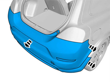
| | Note!
Note the location of the components. |
|
|  | | IMG-333941 |
|
| | |
|  | | IMG-333942 |
|
| | |
|  | | IMG-333943 |
|
| | |
|  | | IMG-333944 |
|
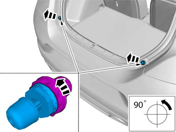
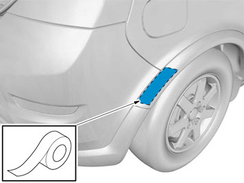
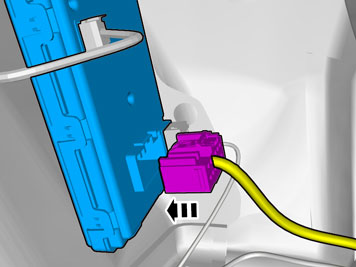
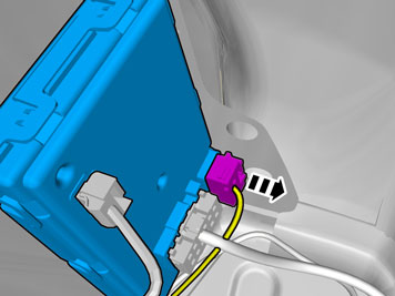
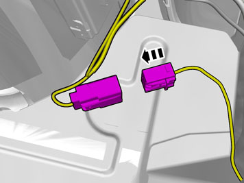
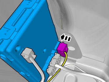
| | Disconnect the connector for the license plate lighting, on the left-hand side. If the car has rear parking assistance, disconnect the connector on the right-hand side. Remove the pieces of tape.
|
|  | | IMG-241183 |
|
| | |
|  | | IMG-241184 |
|
| | |
|  | | IMG-241185 |
|
| | |
|  | | IMG-246643 |
|
| | Fold the central arm rest forward. Remove the central arm rest by grasping each end and pulling upwards until it releases at the rear edge from the backrest's lugs (1). Then pull forwards until the holders (2) on the sides of the backrest have slid out of the corresponding cut-out (3) in the central arm rest.
|
|  | | IMG-241186 |
|
| | |
|  | | IMG-241187 |
|
| | |
|  | | IMG-241188 |
|
| | |
|  | | IMG-241193 |
|
| | |
|  | | IMG-241196 |
|
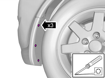
| | Remove the screw from the left-hand panel in the rear seat. Carefully pull the panel from the body side and unhook it from the sill panel at the front edge. It is secured by eleven clips on the inside.
|
|  | | IMG-241199 |
|
| | Remove the clips at the rear edge of the left-hand rear side panel. Carefully pull the side panel off, starting at the front edge/upper edge and then straight back until all clips at the top edge have released. Fold the panel inwards. Release it from the anchorage eyelets and lift it out of the load floor support. Repeat steps 15-22 on the right-hand side.
|
|  | | IMG-241200 |
|
| | |
|  | | IMG-241201 |
|
| | |
| | |
|  | | IMG-249867 |
|
| | |
|  | | IMG-249868 |
|
| | |
|  | | IMG-249869 |
|
| | |
|  | | IMG-260563 |
|
| | Take the trailer connector with cable harness, screws and nuts from the kit. Tighten the trailer connector with cable harness to the bracket on the left-hand side of the towbar with the screws and nuts. Pull the cable in front of the lower and behind the upper screw/spacer sleeve to the hook mounting (Small image), and pull it up on the front of the collision member.
|
| | |
|  | | J8903624 |
|
| | |
|  | | IMG-249871 |
|
| | |
|  | | IMG-249872 |
|
| | |
|  | | IMG-359547 |
|
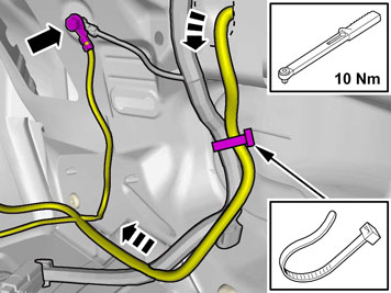
| | Pull the cable harness from the towbar. Connect the ground lead to the existing ground terminal. Tighten the screw. Tighten to 10 Nm (7.5 lbf.ft.) Secure the cable at the existing cable harness using a tie strap.
|
|  | | IMG-347737 |
|
| | Use: Electrician's screwdriver |
|  | | IMG-359666 |
|
| | Position | Cable | Function | 1 | Pink | Reversing lamp | 2 | | Not used | 3 | White | Ground | 4 | | Not used | 5 | Grey | Power supply | 6 | | Not used | 7 | Brown | Right parking lamps | 8 | Black | Left parking lamps | 9 | Green | Right indicator lamps | 10 | Yellow | Left indicator lamps | 11 | Red | Brake lamp | 12 | Blue | Fog lights |
|
|  | | IMG-227863 |
|
| | |
|  | | IMG-359556 |
|
| | |
|  | | IMG-359557 |
|
| | |
|  | | IMG-359559 |
|
| | |
|  | | IMG-359558 |
|
| | |
|  | | IMG-348017 |
|
| | Note!
For correct function, the trailer module (TRM) must be programmed with software before checks can be carried out. |
Note!
To activate the trailer module (TRM) at least two light sources (lamps) must be connected. This can be done by connecting test equipment for the trailer connector or a trailer. |
Position | Function | 1 | Left indicator lamps | 2 | Rear fog lamp | 3 | Ground | 4 | Right indicator lamps | 5 | Right rear position lamp | 6 | Brake lamp | 7 | Left rear running light | 8 | Tail lamp | 9 | Power supply | 10 | Charging | 11 | Charging Ground | 12 | Trailer indicator | 13 | Ground |
|
| | |