| | |
|  | | IMG-295923 |
|
| | |
|  | | IMG-218385 |
|
| | |
|  | | IMG-222340 |
|
| | |
|  | | IMG-222341 |
|
| | |
|  | | IMG-222342 |
|
| | |
|  | | IMG-332180 |
|
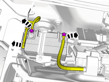
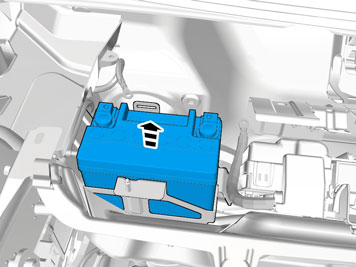
| | Note!
Wait at least one minute before unplugging the connectors or removing other electrical equipment. |
|
|  | | IMG-218386 |
|
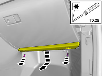
| | Remove the clips of the wiper shaft panel and remove the panel. |
| | Applies to cars with auxiliary battery |
|  | | IMG-359102 |
|
| | |
|  | | IMG-359103 |
|
| | |
|  | | IMG-359104 |
|
| | |
|  | | IMG-359105 |
|
| | Remove the sun roof base plate |
|  | | IMG-359108 |
|
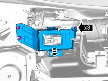
| | Remove the nuts and the bracket |
| | |
|  | | IMG-354313 |
|
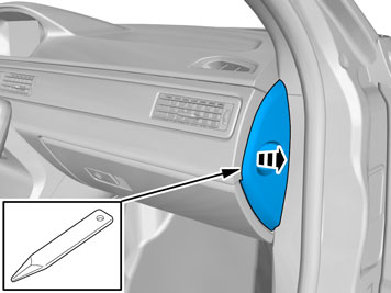
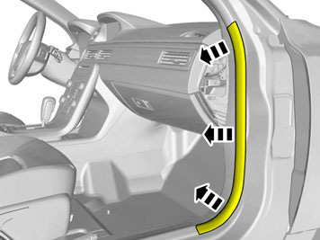
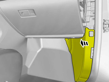
| | Remove the right end panel of the dashboard. |
|  | | IMG-354315 |
|
| | |
|  | | IMG-286863 |
|
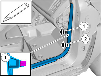
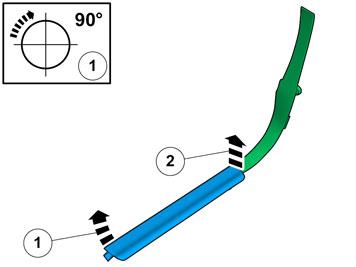
| | Note!
Remove the front and upper sill panel as one unit. |
|
|  | | IMG-308355 |
|
| | |
|  | | IMG-344930 |
|
| | |
|  | | IMG-354320 |
|
| | |
|  | | IMG-303483 |
|
| | |
|  | | IMG-354295 |
|
| | |
|  | | IMG-303484 |
|
| | |
|  | | IMG-355782 |
|
| | |
|  | | IMG-355781 |
|
| | |
|  | | IMG-357907 |
|
| | |
|  | | IMG-357908 |
|
| | |
|  | | IMG-357382 |
|
| | |
|  | | IMG-356889 |
|
| | |
|  | | IMG-225202 |
|
| | Note!
Take care when drilling as many cables go through the rubber grommet. |
|
|  | | IMG-356796 |
|
| | |
|  | | IMG-222277 |
|
| | |
|  | | IMG-284623 |
|
| | |
|  | | IMG-257987 |
|
| | |
|  | | IMG-258363 |
|
| | |
|  | | IMG-258364 |
|
| | Caution!
Make sure that the routing of the antenna cable does not interfere with the function of the inflatable curtain. |
Route the antenna cable along the existing cable at the A-pillar, in toward the dashboard and down toward the floor. Clamp the antenna cable at the existing cable harness using three tie straps from the kit.
|
|  | | IMG-222282 |
|
| | |
|  | | IMG-222283 |
|
| | |
|  | | IMG-222284 |
|
| | |
|  | | IMG-222285 |
|
| | |
|  | | IMG-222286 |
|
| | |
|  | | IMG-356651 |
|
| | Move the floor and insulating mats out of the way. |
|  | | IMG-222288 |
|
| | Scrape away all sealing compound from the flat surface at the bottom edge of the A-pillar where the receiver unit for remote start will sit. The top part of the receiver unit should be 30 mm (1 3/16 ") from the bottom edge of the lower hole in the body. Clean the surface using isopropanol and wipe dry.
|
|  | | IMG-222287 |
|
| | |
|  | | IMG-222289 |
|
| | |
|  | | IMG-284624 |
|
| | |
|  | | IMG-372106 |
|
| | |
|  | | IMG-372107 |
|
| | |
|  | | IMG-372108 |
|
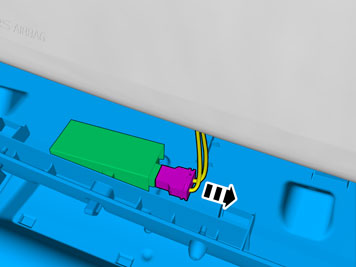
| | Connect the red (R) cable to the 6-pin connector. Press the secondary catch together. |
|  | | IMG-235860 |
|
| | |
|  | | IMG-235861 |
|
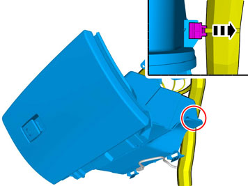
| | Plug in the adapter cable connectors to the corresponding parking heater cable connectors that were unplugged before. Use tie straps from the kit to secure the cables and connectors to existing cables to prevent rattling.
|
|  | | IMG-336901 |
|
| | |
|  | | IMG-257992 |
|
| | Synchronising the transmitter and receiver Connect the aerial cable to the receiver unit. Connect the connector to the receiver unit. Within the time interval 1.5 to 5 seconds, press the "OFF" button on the transmitter until the LED goes out. The LED on the transmitter must then light red continuously for 2 seconds and then go out.
Note!
if the LED lights for 2 seconds and then goes out, synchronisation has failed. |
Tape up cable excess and relay and place beside the control module under the insulation. |
| | Install removed parts in reverse order. Torque tighten the nuts for the wiper arms to 30 ± 3 Nm (22 ± 2 lbf.ft.). |
|  | | IMG-336904 |
|
| | Warning!
When the ignition is to be switched on for the first time after the battery has been disconnected, this must be done whilst by standing outside the vehicle, stretching your arm in and avoiding the working area for the airbags. |
|
|  | | IMG-242268 |
|
| | Download the software (application) for the accessory's function following the service information in VIDA. See VIDA or the accessories catalogue for software part number. |
| | |
|  | | IMG-360922 |
|
| | Press the "ON" button on the transmitter, the LED on the transmitter must then light green for 2 seconds. The signal from the remote start to the car has therefore gone through but the control module for the heater in the car determines whether to turn the heater on or not. Press the "OFF" button on the transmitter, the LED on the transmitter must then light red for 2 seconds. The signal from the remote start to the car has therefore gone through. Note!
if the LED flashes instead of illuminating continuously, see the remote start's owner manual for further information about the fault. |
Note!
the heater does not start if e.g.: |
The temperature exceeds 15 degrees C. The battery in the car has insufficient charge The fuel level in the tank is too low. |