| | |
|  | | IMG-363036 |
|
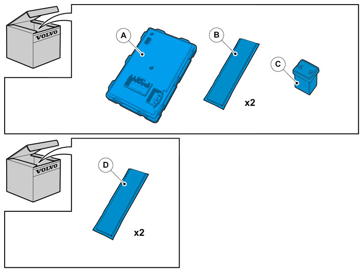
| | Color symbols Used for focused part, the part that you are to do something with. Used as extra colors when you need to show or highlight additional parts. Used for fasteners to be removed/installed. May be screws, clips, connectors, etc. Used when part is not removed completely from the vehicle but is only hung/suspended off to the side. Used for standard tools and special tools. Used as background color on vehicle parts.
|
|  | | IMG-245980 |
|
| | |
|  | | IMG-226720 |
|
| | |
|  | | IMG-226722 |
|
| | |
| | |
|  | | IMG-226723 |
|
| | |
|  | | IMG-226724 |
|
| | Remove: the three clips in the top edge of the side panel. the four plastic nuts in the lower edge of the side panel. the connector for the trunk lighting. Lift out the side panel.
|
|  | | IMG-360485 |
|
| | |
|  | | IMG-360486 |
|
| | |
|  | | IMG-356181 |
|
| | |
|  | | IMG-222282 |
|
| | |
|  | | IMG-241925 |
|
| | |
|  | | IMG-360498 |
|
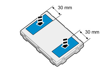
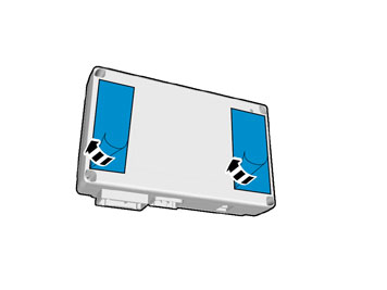
| | When installing Velcro tape the surface must maintain a temperature of at least +20 ° C (68°F). |
|  | | IMG-360492 |
|
| | |
|  | | IMG-360501 |
|
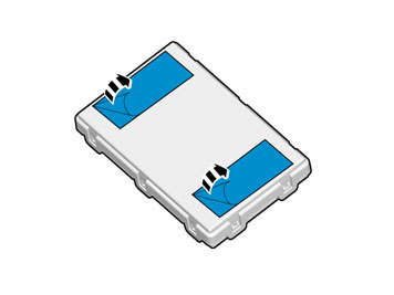
| | When installing Velcro tape the surface must maintain a temperature of at least +20 ° C (68°F). |
|  | | IMG-360526 |
|
| | Applies to cars equipped with rear parking camera. |
|  | | IMG-360527 |
|
| | |
|  | | IMG-360528 |
|
| | |
|  | | IMG-360529 |
|
| | |
|  | | IMG-360548 |
|
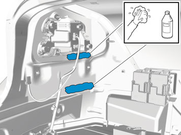
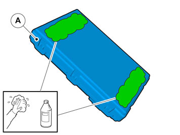
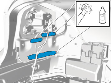
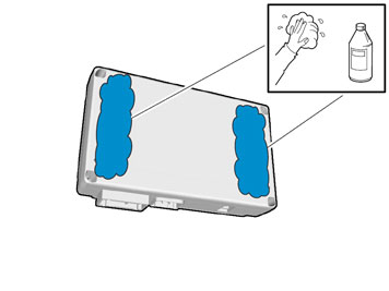
| | Use:Isopropanol, 1161721 Wipe off. |
|  | | IMG-360549 |
|
| | Use:Isopropanol, 1161721 Wipe off. |
| | |
|  | | IMG-361618 |
|
| | |
| | | IMG-222282 |
|
| | |
| | | IMG-241925 |
|
| | |
|  | | IMG-360550 |
|
| | When installing Velcro tape the surface must maintain a temperature of at least +20 ° C (68°F). |
|  | | IMG-360551 |
|
| | |
|  | | IMG-360552 |
|
| | When installing Velcro tape the surface must maintain a temperature of at least +20 ° C (68°F). |
| | | IMG-360486 |
|
| | |
| | | IMG-356181 |
|
| | |
| | | IMG-222282 |
|
| | |
| | | IMG-241925 |
|
| | |
| | | IMG-360498 |
|
| | When installing Velcro tape the surface must maintain a temperature of at least +20 ° C (68°F). |
| | | IMG-360492 |
|
| | |
|  | | IMG-360577 |
|
| | When installing Velcro tape the surface must maintain a temperature of at least +20 ° C (68°F). |
|  | | IMG-360576 |
|
| | |
|  | | IMG-360508 |
|
| | |
|  | | IMG-360521 |
|
| | |
|  | | IMG-368463 |
|
| | Installing trailer hitch cable harness |
|  | | IMG-368465 |
|
| | |
|  | | IMG-368466 |
|
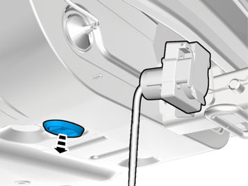
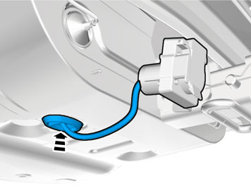
| | Insert the cable with the connector into the hole in the spare wheel well and install the rubber grommet. Adapt the length of the cable from the connector to the rubber grommet so that the cable is not too slack beneath the car.
Note!
Install the rubber grommet so that the cable points to the left on the inside. |
|
|  | | IMG-368472 |
|
| | |
|  | | IMG-368467 |
|
| | |
|  | | IMG-361392 |
|
| | |
|  | | IMG-368468 |
|
| | |
|  | | IMG-368474 |
|
| | |
|  | | IMG-360159 |
|
| | |
|  | | IMG-361631 |
|
| | |
| | |
|  | | IMG-242268 |
|
| | |
|  | | IMG-249951 |
|
| | Checking the trailer connector 7-pin connection Brake lamp / Left-hand indicator lamp Ground Spare (Brake lamp, Electric brakes) Brake lamp / Right-hand indicator lamp Charging Position lamps Spare (Reversing lamp)
The cable for pin 3 for 7-pin connection is blue (BL). It is taped on the cable harness approx. 1 meter from the trailer socket. 4-pin connection Brake lamp / Right-hand indicator lamp Brake lamp / Left-hand indicator lamp Position lamps Ground
|