| | |
|  | | IMG-245980 |
|
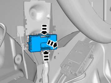
| | Note!
Wait at least one minute before unplugging the connectors or removing other electrical equipment. |
|
| | |
|  | | IMG-339894 |
|
| | |
|  | | IMG-340180 |
|
| | |
|  | | IMG-340028 |
|
| | |
|  | | IMG-339896 |
|
| | |
|  | | IMG-340029 |
|
| | |
|  | | IMG-340229 |
|
| | |
|  | | IMG-340231 |
|
| | |
|  | | IMG-340237 |
|
| | |
|  | | IMG-340241 |
|
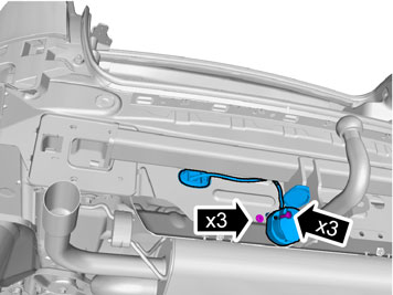
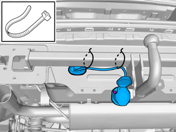
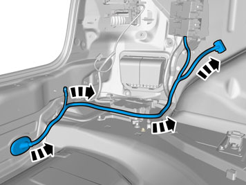
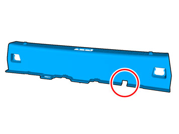
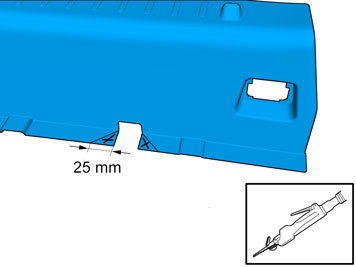
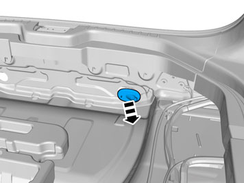
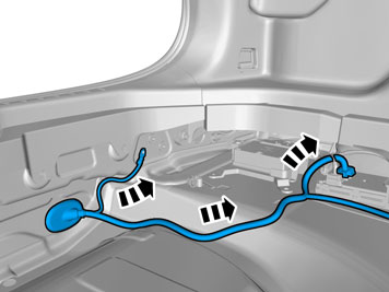
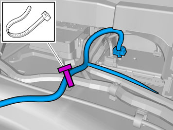
| | Adjust the cable length from the contact to the rubber grommet as illustrated. Press the rubber grommet into the rear crossmember. Install the contact with screws and nuts from the kit.
|
|  | | IMG-340255 |
|
| | |
|  | | IMG-361557 |
|
| | |
|  | | IMG-361552 |
|
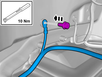
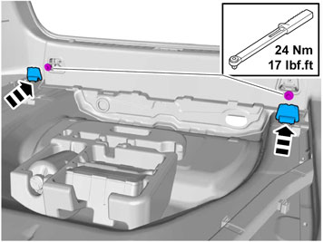
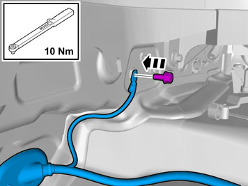
| | Take the ground screw from the kit and secure the ground lead to the ground terminal on the left-hand side in the rear crossmember. Torque tighten the screw, tightening torque: 10 Nm (7.5 lbf.ft.).
|
|  | | IMG-361564 |
|
| | |
|  | | IMG-361566 |
|
| | |
|  | | IMG-340109 |
|
| | |
|  | | IMG-340267 |
|
| | |
|  | | IMG-340349 |
|
| | |
|  | | IMG-347024 |
|
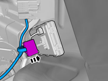
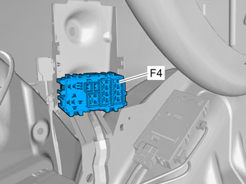
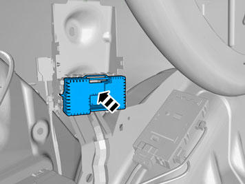
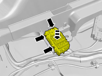
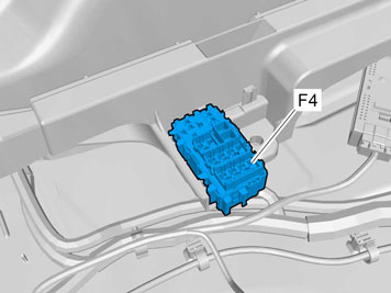
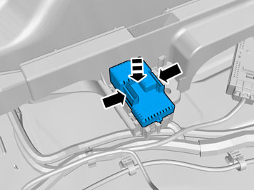
| | Carefully pry between the front and rear section of the fuse holder using a weatherstrip tool so that the black front section is moved to the side slightly. Install the routed single cable on the rear of fuse terminal F4 in the spare socket. Reinstall the catch in the rear section.
|
|  | | IMG-347025 |
|
| | |
|  | | IMG-340268 |
|
| | |
|  | | IMG-340271 |
|
| | |
|  | | IMG-340052 |
|
| | |
|  | | IMG-361612 |
|
| | Only applies to detachable towbar |
|  | | IMG-340280 |
|
| | |
|  | | IMG-340201 |
|
| | |
|  | | IMG-339899 |
|
| | |
| | |
|  | | IMG-348017 |
|
| | Note!
For correct function, the trailer module (TRM) must be programmed with software before checks can be carried out. |
Note!
To activate the trailer module (TRM) at least two light sources (lamps) must be connected. This can be done by connecting test equipment for the trailer connector or a trailer. |
Position - Function Left-hand indicator Rear fog lamps Ground terminal Right-hand indicator Right parking lamps Brake lamp Left parking lamps Reversing lamp Battery voltage, constant Battery voltage, ignition on Ground terminal Not connected. Ground terminal
|
|  | | IMG-342225 |
|
| | |
|  | | IMG-342227 |
|
| | |
| | | IMG-340229 |
|
| | |
|  | | IMG-342235 |
|
| | |
| | | IMG-340237 |
|
| | |
| | | IMG-340241 |
|
| | Adjust the cable length from the contact to the rubber grommet as illustrated. Press the rubber grommet into the rear crossmember. Install the contact with screws and nuts from the kit.
|
| | | IMG-340255 |
|
| | |
|  | | IMG-361571 |
|
| | |
|  | | IMG-361572 |
|
| | Take the ground screw from the kit and secure the ground lead to the ground terminal on the left-hand side in the rear crossmember. Torque tighten the screw, tightening torque: 10 Nm.
|
|  | | IMG-361573 |
|
| | |
|  | | IMG-361576 |
|
| | |
|  | | IMG-342228 |
|
| | |
|  | | IMG-342238 |
|
| | |
| | | IMG-340349 |
|
| | |
| | | IMG-347024 |
|
| | Carefully pry between the front and rear section of the fuse holder using a weatherstrip tool so that the black front section is moved to the side slightly. Install the routed single cable on the rear of fuse terminal F4 in the spare socket. Reinstall the catch in the rear section.
|
| | | IMG-347025 |
|
| | |
|  | | IMG-342237 |
|
| | |
|  | | IMG-342239 |
|
| | |
|  | | IMG-342229 |
|
| | |
| | |
| | | IMG-348017 |
|
| | Note!
For correct function, the trailer module (TRM) must be programmed with software before checks can be carried out. |
Note!
To activate the trailer module (TRM) at least two light sources (lamps) must be connected. This can be done by connecting test equipment for the trailer connector or a trailer. |
Position - Function Left-hand indicator Rear fog lamps Ground terminal Right-hand indicator Right parking lamps Brake lamp Left parking lamps Reversing lamp Battery voltage, constant Battery voltage, ignition on Ground terminal Not connected. Ground terminal
|