| | |
| | Read through all of the instructions before starting installation. Notifications and warning texts are for your safety and to minimise the risk of something breaking during installation. Ensure that all tools stated in the instructions are available before starting installation. Certain steps in the instructions are only presented in the form of images. Explanatory text is also given for more complicated steps. In the event of any problems with the instructions or the accessory, contact your local Volvo dealer.
|
| | |
| | These installation instructions show installation on left hand drive cars. When installing on right-hand drive cars, perform the procedures on the opposite side and/or mirrored. Where the procedure differs, the right-hand version is also shown with text and image. |
| | |
|  | | IMG-363036 |
|
| | Note!
This colour chart displays (in colour print and electronic version) the importance of the different colours used in the images of the method steps. |
Used for focused component, the component with which you will do something. Used as extra colors when you need to show or differentiate additional parts. Used for attachments that are to be removed/installed. May be screws, clips, connectors, etc. Used when the component is not fully removed from the vehicle but only hung to the side. Used for standard tools and special tools. Used as background color for vehicle components.
|
| | |
|  | | IMG-380122 |
|
| | |
|  | | IMG-380123 |
|
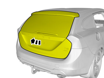
| | Clean the surface. Use: 1161721, Isopropanol
|
|  | | IMG-380131 |
|
| | Matt the surface gently. Use: , Sand paper P1000
|
| | | IMG-380123 |
|
| | Clean the surface. Use: 1161721, Isopropanol
|
|  | | IMG-380132 |
|
| | Caution!
Protect connector surfaces against paint spray. |
Note!
Use correct color following the vehicle's paint code. |
Use: , Volvo Original Touch-up paint
Use base coat only. Also see the instructions on the container. Allow to dry. |
| | | IMG-380132 |
|
| | Use: 31335447, Varnish 2-component
Also see the instructions on the container. Allow to dry. |
|  | | IMG-380178 |
|
| | Caution!
First the paint must dry after painting. |
|
| | |
|  | | IMG-332193 |
|
| | Set the ignition key to position 0. |
|  | | IMG-292804 |
|
| | |
|  | | IMG-292806 |
|
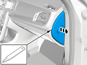
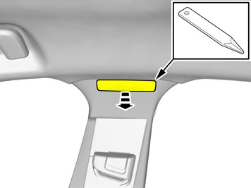
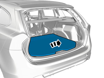
| | Fold the carpet to the side. |
|  | | IMG-292823 |
|
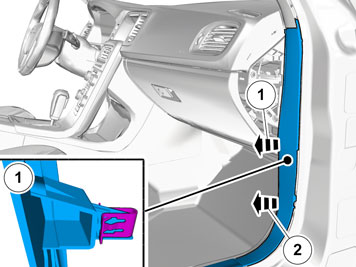
| | Unhook the cable harness clips. Disconnect the connector. |
|  | | IMG-292826 |
|
| | |
|  | | IMG-292827 |
|
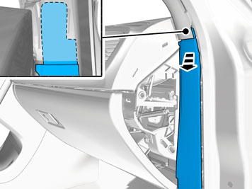
| | Disconnect the connector, if applicable. |
|  | | IMG-346236 |
|
| | |
|  | | IMG-340984 |
|
| | Disconnect the connector. |
|  | | IMG-340985 |
|
| | |
|  | | IMG-355818 |
|
| | |
| | Cars with automatic transmissions |
|  | | IMG-293006 |
|
| | |
|  | | IMG-293007 |
|
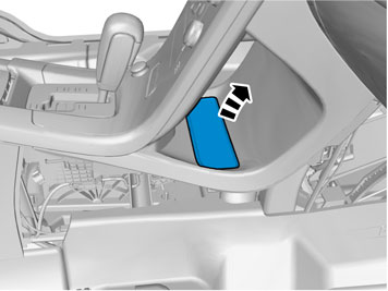
| | Release the shift-lock function. |
| | |
|  | | IMG-340981 |
|
| | |
| | Cars with manual transmissions |
|  | | IMG-345292 |
|
| | |
| | |
|  | | IMG-340604 |
|
| | Disconnect the connector. |
|  | | IMG-340605 |
|
| | |
|  | | IMG-340607 |
|
| | |
|  | | IMG-381763 |
|
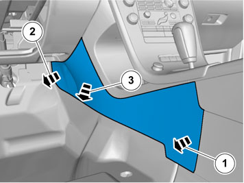
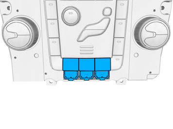
| | Select the first free position closest to the driver. |
| | |
|  | | IMG-396256 |
|
| | If all locations for the switch are occupied a switch with function must be removed in priority order as illustrated. BLIS Distance Alert Lane depature warning (LDW)
|
| | Right-hand drive vehicles |
|  | | IMG-396255 |
|
| | If all locations for the switch are occupied a switch with function must be removed in priority order as illustrated. BLIS Distance Alert Lane depature warning (LDW)
|
| | |
|  | | IMG-380450 |
|
| | |
| | |
|  | | IMG-380454 |
|
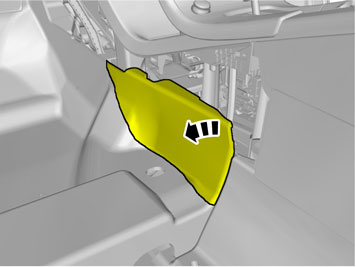
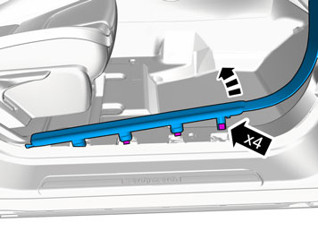
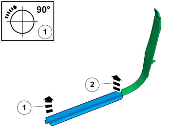
| | Install component that comes with the accessory kit. |
| | |
|  | | IMG-341739 |
|
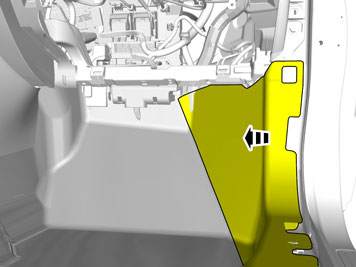
| | Reinstall the removed part. |
| | | IMG-340605 |
|
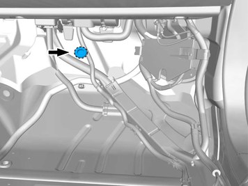
| | |
|  | | IMG-340622 |
|
| | |
| | |
|  | | IMG-344926 |
|
| | |
|  | | IMG-344927 |
|
| | |
|  | | IMG-344928 |
|
| | Caution!
The front and upper sill panel must be removed and installed as one unit. |
|
|  | | IMG-344929 |
|
| | |
|  | | IMG-344930 |
|
| | |
|  | | IMG-344451 |
|
| | |
|  | | IMG-375379 |
|
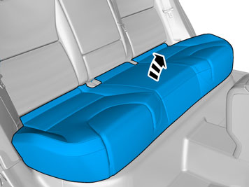
| | Fold the carpet to the side. |
|  | | IMG-396281 |
|
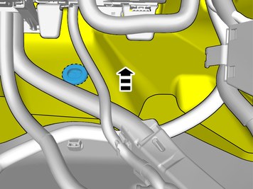
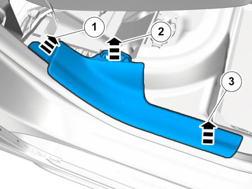
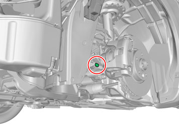
| | Locate the rubber grommet under the insulating mat. |
|  | | IMG-396796 |
|
| | Fold the insulation to one side. |
|  | | IMG-385185 |
|
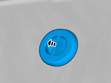
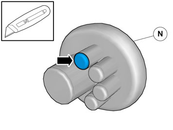
| | Remove the marked part. The part is not to be reused. |
|  | | IMG-342372 |
|
| | Repeat on the other side. |
|  | | IMG-341902 |
|
| | Disconnect the connector, if applicable. Repeat on the other side. |
|  | | IMG-360124 |
|
| | |
|  | | IMG-341906 |
|
| | |
|  | | IMG-382077 |
|
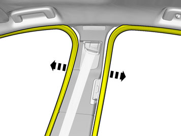
| | Remove the weatherstrips. |
|  | | IMG-382078 |
|
| | |
|  | | IMG-382079 |
|
| | |
|  | | IMG-382080 |
|
| | |
|  | | IMG-382081 |
|
| | |
|  | | IMG-382090 |
|
| | |
|  | | IMG-346181 |
|
| | |
|  | | IMG-343412 |
|
| | |
|  | | IMG-343413 |
|
| | |
|  | | IMG-352021 |
|
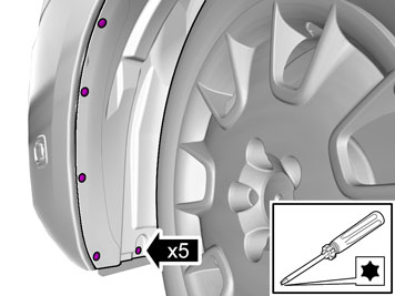
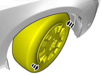
| | Caution!
Left side! This step applies also to right-hand drive vehicles! |
Tightening torque: Wheel to wheel hub
Stage 1:
20 Nm
Stage 2:
140 Nm
|
|  | | IMG-381634 |
|
| | |
|  | | IMG-381635 |
|
| | Disconnect the connector. |
|  | | IMG-381636 |
|
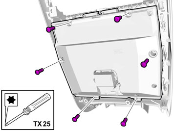
| | Remove the screw. Remove the marked part. The part is not to be reused. |
| | |
|  | | IMG-381633 |
|
| | Caution!
Left side! This step applies also to right-hand drive vehicles! |
Note!
Make sure that the mating faces are clean and free of foreign material. |
|
|  | | IMG-381637 |
|
| | Install component that comes with the accessory kit.
Tightening torque: M5
, 5 Nm
|
|  | | IMG-381638 |
|
| | |
| | |
|  | | IMG-341913 |
|
| | |
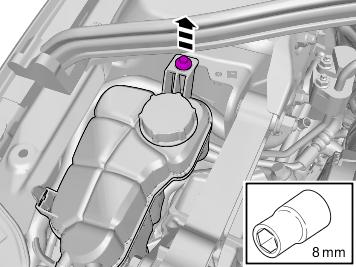
| | Vehicles with headlamp washers |
|  | | IMG-341914 |
|
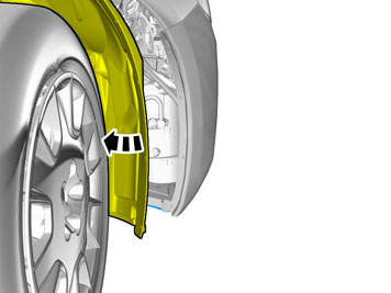
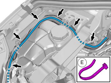
| | Fold the wing liner to one side. |
|  | | IMG-341915 |
|
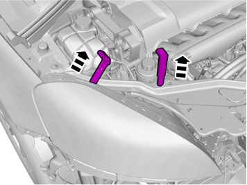
| | Warning!
Be prepared to collect escaping fluid. |
Note!
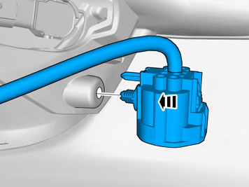
Tape the hose high up on the washer fluid reservoir to prevent washer fluid from coming out. |
Take a piece of washer hose. Tie a knot in it and place it on the washer pump to prevent the washer fluid reservoir from emptying.
|
| | Right-hand drive vehicles |
|  | | IMG-341916 |
|
| | |
|  | | IMG-341917 |
|
| | |
|  | | IMG-341918 |
|
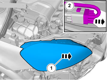
| | Fold the wing liner to one side. |
| | |
|  | | IMG-382362 |
|
| |
Tightening torque: Wheel to wheel hub
Stage 1:
20 Nm
Stage 2:
140 Nm
|
|  | | IMG-382364 |
|
| | |
|  | | IMG-382363 |
|
| | |
|  | | IMG-382366 |
|
| | |
|  | | IMG-382367 |
|
| | |
|  | | IMG-382368 |
|
| | |
| | |
|  | | IMG-378274 |
|
| | |
|  | | IMG-378285 |
|
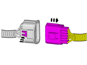
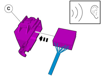
| | Depress the locking device. Disconnect the connector.
|
|  | | IMG-307687 |
|
| | Release the locks. RHD: The procedure is carried out on the opposite side. |
|  | | IMG-307688 |
|
| | Remove the marked part. Disconnect the connector. RHD: The procedure is carried out on the opposite side. |
|  | | IMG-341924 |
|
| | |
|  | | IMG-341927 |
|
| | |
|  | | IMG-382096 |
|
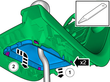
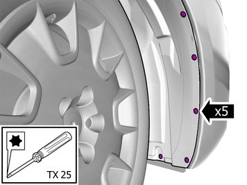
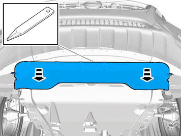
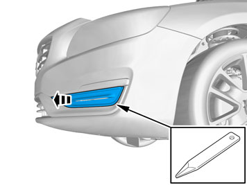
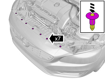
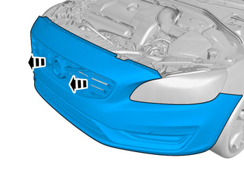
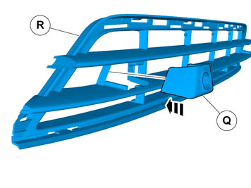
| | Remove the clips. Remove the screws. Remove the marked part. |
|  | | IMG-382097 |
|
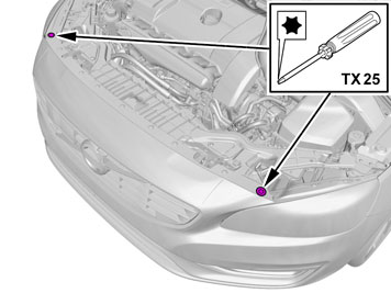
| | Remove the clip. Remove the screws. Remove the marked part. |
|  | | IMG-378560 |
|
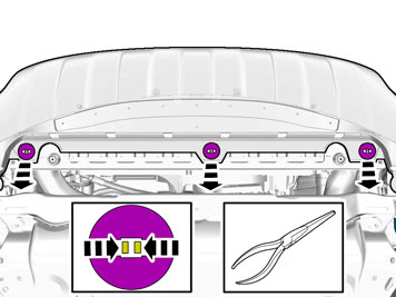
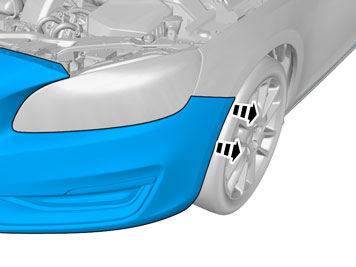
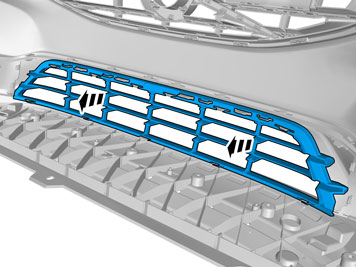
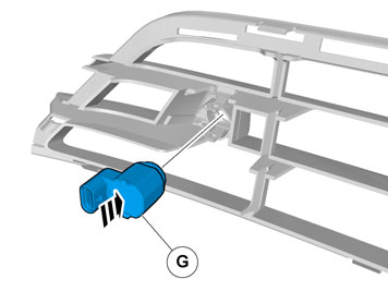
| | Remove the marked part. The part is not to be reused. Repeat on the other side. |
|  | | IMG-378108 |
|
| | |
|  | | IMG-378111 |
|
| | |
|  | | IMG-378561 |
|
| | Repeat on the other side. |
|  | | IMG-378577 |
|
| | Caution!
Place the Bumper Cover on a suitable surface. |
|
|  | | IMG-380218 |
|
| | Locate the markings for the positions. |
|  | | IMG-380219 |
|
| | |
|  | | IMG-380220 |
|
| | |
|  | | IMG-380221 |
|
| |
Use special tool: T9997234, Hole stamp
|
|  | | IMG-380222 |
|
| | Clean the surface. Use: 1161721, Isopropanol
|
|  | | IMG-380230 |
|
| | Clean the surface. Use: 1161721, Isopropanol
|
|  | | IMG-380223 |
|
| | Use: 1161765, Primer
Allow to dry for at least 2 minutes, but no more than 60minutes. |
|  | | IMG-380231 |
|
| | Use: 1161765, Primer
Allow to dry for at least 2 minutes, but no more than 60minutes. |
|  | | IMG-378579 |
|
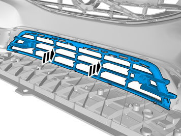
| | The part is not to be reused. |
| | |
|  | | IMG-378581 |
|
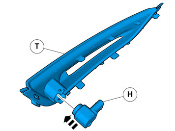
| | Repeat on the other side. |
|  | | IMG-378583 |
|
| | Repeat on the other side. |
|  | | IMG-378584 |
|
| | |
|  | | IMG-382218 |
|
| | |
|  | | IMG-382219 |
|
| | |
|  | | IMG-378590 |
|
| | |
|  | | IMG-378591 |
|
| | Repeat on the other side. |
|  | | IMG-380257 |
|
| | Note!
Prepare and install one holder at a time. |
|
|  | | IMG-380259 |
|
| | Note!
Ensure that the tape is fixed to the surface. |
|
|  | | IMG-380264 |
|
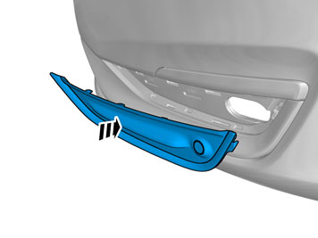
| | Remove the protective film. |
|  | | IMG-380262 |
|
| | Warning!
Wear protective gloves. |
Warning!
Make sure to provide adequate ventilation. |
Use special tool: T9512950, Glue gun (kit)
Use: 1161730, Mixing pipe
Use: 9511027, Glue
|
|  | | IMG-380261 |
|
| | |
|  | | IMG-380275 |
|
| | Note!
Hold the part securely at the marker arrows when removing the tool. |
|
|  | | IMG-380279 |
|
| | Repeat on the other side. |
|  | | IMG-378592 |
|
| | Put the wiring in the Bumper cover without installing the wiring. RHD: The cable harness is positioned mirrored. |
|  | | IMG-380283 |
|
| | |
|  | | IMG-378598 |
|
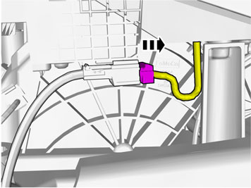
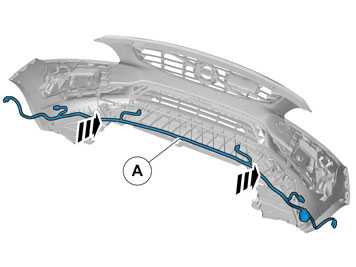
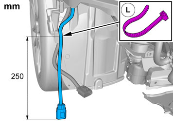
| | Note!
Make sure that the wiring harness is not visible from outside. |
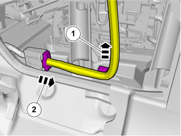
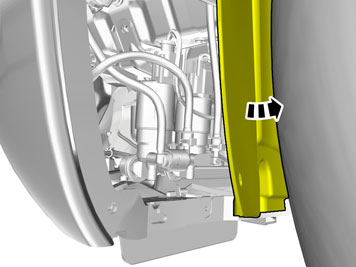
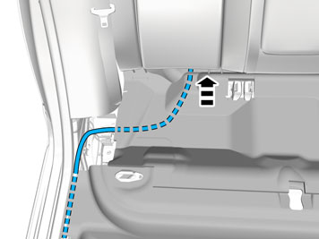
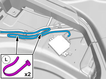
Position/route the cable harness as illustrated. |
|  | | IMG-378596 |
|
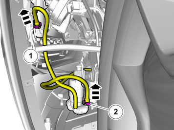
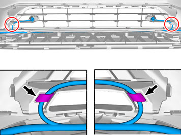
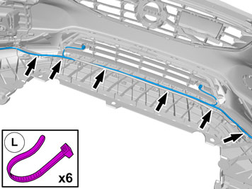
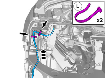
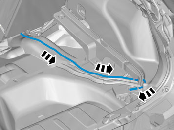
| | Route the cable harness to the existing cable harness. Adjust the position of the wiring harness. Tighten the cable ties. |
|  | | IMG-396898 |
|
| | |
|  | | IMG-380288 |
|
| | Repeat on the other side. |
|  | | IMG-378602 |
|
| | |
|  | | IMG-378603 |
|
| | |
| | |
|  | | IMG-373258 |
|
| | |
|  | | IMG-382238 |
|
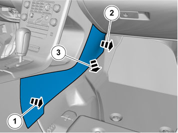
| | Position/route the cable harness as illustrated. |
|  | | IMG-382240 |
|
| | Position/route the cable harness as illustrated. |
|  | | IMG-385294 |
|
| | |
|  | | IMG-385291 |
|
| | |
|  | | IMG-385299 |
|
| | Position/route the cable harness as illustrated. |
|  | | IMG-382242 |
|
| | Remove the screws. Remove the marked part. |
|  | | IMG-382377 |
|
| | Position/route the cable harness as illustrated. |
|  | | IMG-382375 |
|
| | |
|  | | IMG-382372 |
|
| |
Use special tool: T9512932, Tension spring
|
|  | | IMG-382378 |
|
| | |
|  | | IMG-382381 |
|
| | |
|  | | IMG-382388 |
|
| | Note!
On some markets the rubber grommet may be covered by the heat shield. |
|
|  | | IMG-382389 |
|
| | Pull the wiring through. Remove the Special Tool. |
|  | | IMG-382392 |
|
| | Position/route the cable harness as illustrated. |
|  | | IMG-382393 |
|
| | Position/route the cable harness as illustrated. |
|  | | IMG-382395 |
|
| | |
|  | | IMG-382399 |
|
| | |
| | Right-hand drive vehicles |
| | | IMG-373258 |
|
| | |
|  | | IMG-382245 |
|
| | Position/route the cable harness as illustrated. |
|  | | IMG-382246 |
|
| | Position/route the cable harness as illustrated. |
|  | | IMG-382247 |
|
| | Position/route the cable harness as illustrated. |
|  | | IMG-382258 |
|
| | Position/route the cable harness as illustrated. |
|  | | IMG-382262 |
|
| | |
|  | | IMG-396813 |
|
| | |
| | |
|  | | IMG-372722 |
|
| | |
|  | | IMG-382174 |
|
| | |
|  | | IMG-382176 |
|
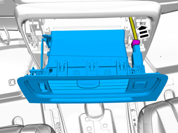
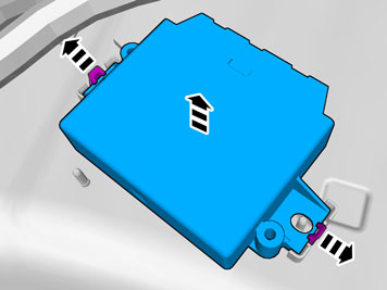
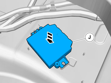
| | Place the component where indicated in the graphic. |
|  | | IMG-382175 |
|
| | |
|  | | IMG-382183 |
|
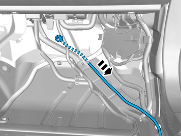
| | Note!
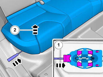
Push the rubber grommet well through the hole. |
Route the wiring harness into the passenger compartment. |
| | | IMG-396281 |
|
| | |
|  | | IMG-382178 |
|
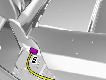
| | Caution!
Make sure that the rubber grommet seals properly to the body. |
|
|  | | IMG-396275 |
|
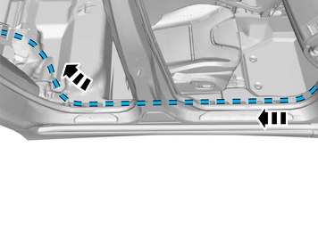
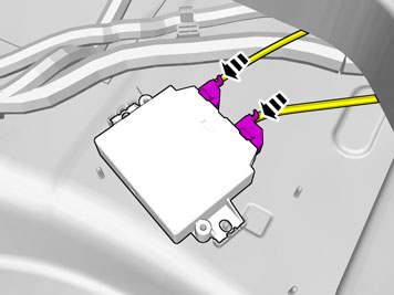
| | Position/route the cable harness as illustrated. |
|  | | IMG-396277 |
|
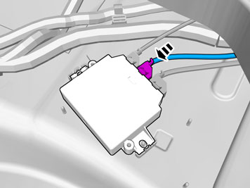
| | Position/route the cable harness as illustrated. |
| | Right-hand drive vehicles |
|  | | IMG-308083 |
|
| | Position/route the cable harness as illustrated. |
| | |
|  | | IMG-378628 |
|
| | Position/route the cable harness as illustrated. |
|  | | IMG-346331 |
|
| | Position/route the cable harness as illustrated. |
| | |
|  | | IMG-361341 |
|
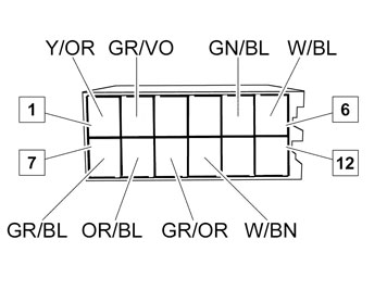
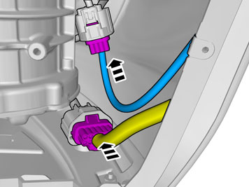
| | Connect the cable harness terminals in the connector as follows. |
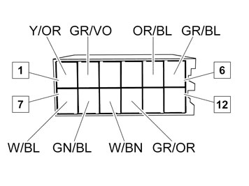
| | Right-hand drive vehicles |
|  | | IMG-361342 |
|
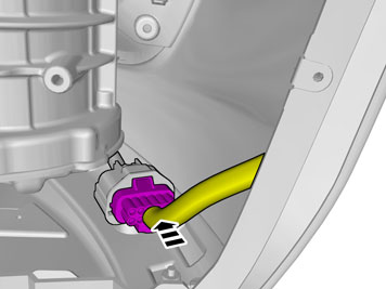
| | Connect the cable harness terminals in the connector as follows. |
| | |
|  | | IMG-361376 |
|
| | |
|  | | IMG-361377 |
|
| | |
|  | | IMG-378052 |
|
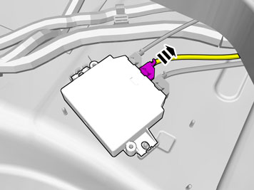
| | Disconnect the connector, if applicable. Attach the connector to the wiring harness. Use: , Electrical tape
The connector is not to be used. |
|  | | IMG-378055 |
|
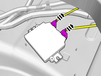
| | Disconnect the connectors. |
|  | | IMG-378062 |
|
| | The part is not to be reused. |
|  | | IMG-378063 |
|
| | Install component that comes with the accessory kit. |
|  | | IMG-378065 |
|
| | |
|  | | IMG-378066 |
|
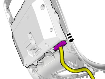
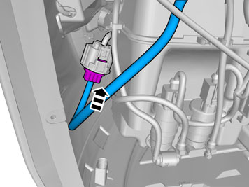
| | Connect the prerouted cable. |
|  | | IMG-378070 |
|
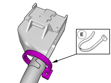
| | Note!
Extra cable length must be secured using cable ties. |
|
| | |
|  | | IMG-378609 |
|
| | Place the Bumper Cover in position for installation. |
| | |
|  | | IMG-378276 |
|
| | |
| | Right-hand drive vehicles |
|  | | IMG-378280 |
|
| | |
|  | | IMG-378611 |
|
| | |
| | Vehicles with headlamp washers |
|  | | IMG-350323 |
|
| | Reinstall the removed parts in reverse order. |
| | |
| | | IMG-378609 |
|
| | |
|  | | IMG-377070 |
|
| | Reinstall the removed parts in reverse order. |
|  | | IMG-242268 |
|
| | Download software (application) for the accessory's function according to the service information in VIDA. |