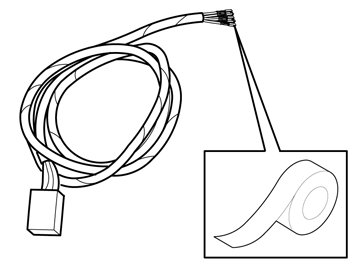
| | Note!
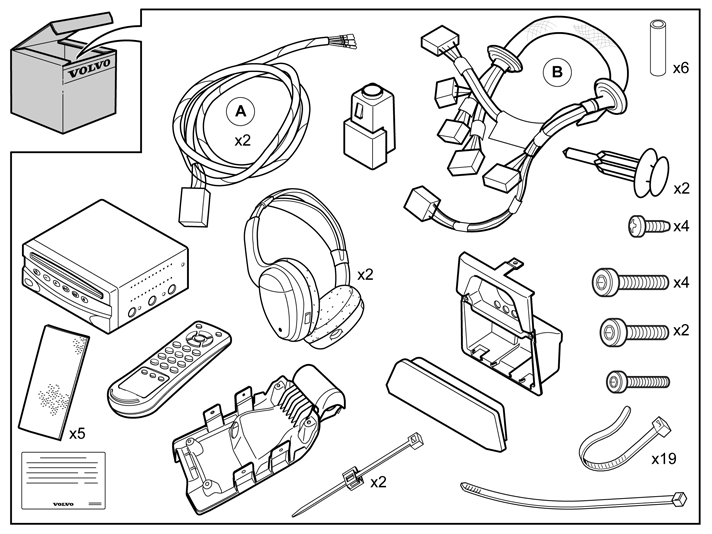
There are two versions of cable harness for the tunnel console, with or without preparations for Digital TV receivers. The images in the installation instructions show cable harness without Digital TV receiver. |
|
|  | | IMG-256044 |
|
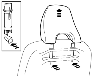
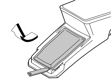
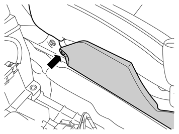
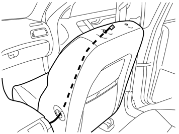
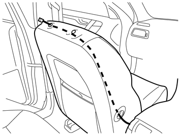
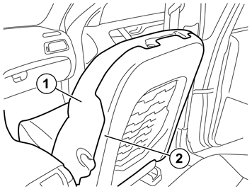
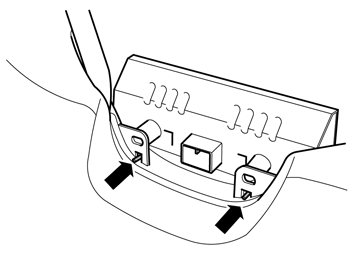
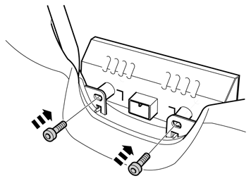
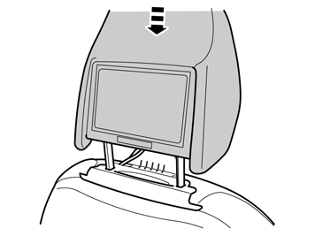
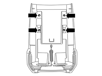
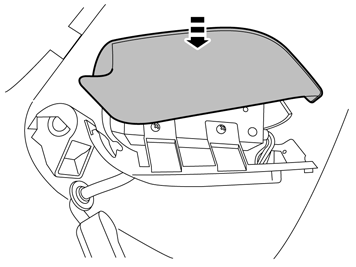
| | Slide both the front seats all the way back and upwards all the way at the front and rear edge. Press the headrest downwards. Find the headrest's two locks on the back of the seat. Press in the catches and pull the headrest upwards at the same time. The seats may require lowering slightly at the rear edge again so that the headrest can be pulled out of the backrest completely. Therefore lower the seat as much as possible so that the headrest can be released and removed. Remove the headrest on both front seats and allow the seats to remain in the same position.
|
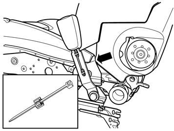
|  | | R8504225 |
|
| | |
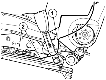
|  | | R8504495 |
|
| | |
|  | | IMG-238927 |
|
| | |
|  | | R8503994 |
|
| | |
|  | | R8504113 |
|
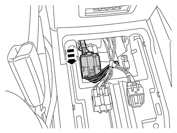
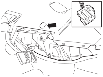
| | Applies to cars with automatic gearbox Applies to all models |
|  | | IMG-245980 |
|
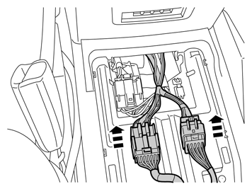
| | Note!
Wait at least three minutes before unplugging the connectors or removing other electrical equipment. |
|
|  | | IMG-239204 |
|
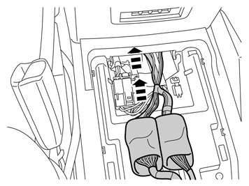
| | |
|  | | IMG-268403 |
|
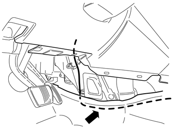
| | |
|  | | R3904067 |
|
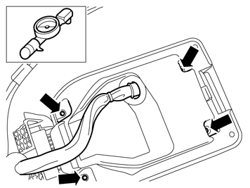
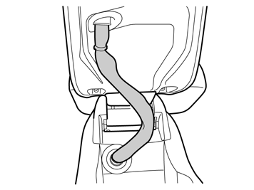
| | Applies to cars with telephone Unhook and disconnect the connector (1). Disconnect the telephone cable from the load-removing grommet (2). Release the telephone cable. Remove the handset. Remove the screw (3). Push the catch to one side (4). Remove the telephone cradle.
|
|  | | IMG-268404 |
|
| | |
|  | | IMG-268405 |
|
| | |
|  | | IMG-268406 |
|
| | |
|  | | IMG-268407 |
|
| | |
|  | | IMG-317323 |
|
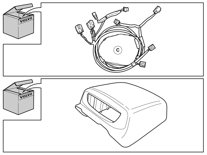
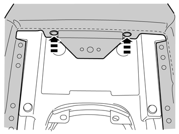
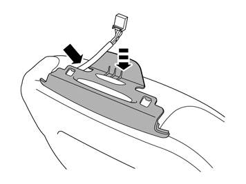
| | Take the cable harness (C) from the kit and position it as illustrated. The junction (1) must be at the rear edge of the SRS control module. The cable marked with blue tape must go to the right seat and the other to the left seat. The cable with 2 x 4 pin connectors must be routed forward on the driver's side.
|
|  | | IMG-268409 |
|
| | |
|  | | IMG-268410 |
|
| | |
|  | | IMG-268411 |
|
| | Carry out points 18-45 on both sides of the seats |
|  | | IMG-268412 |
|
| | |
|  | | IMG-268413 |
|
| | |
|  | | IMG-268414 |
|
| | |
|  | | IMG-262949 |
|
|  | | IMG-317223 |
|
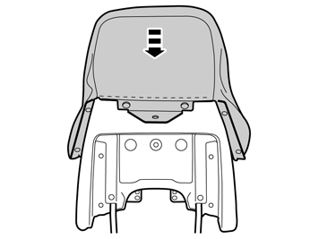
| | Illustrations A and B Remove cable harness (A) from the kit. Tape the cable terminals on the cable tie. Tape together as flat as possible. (Image B) Route the cable harness through and out at the headrest hole. Remove the cable tie from the cable harness.
|
|  | | IMG-262950 |
|
| | Applies to the right-hand front seat |
|  | | IMG-262952 |
|
| | Applies to the left-hand front seat. |
|  | | IMG-262951 |
|
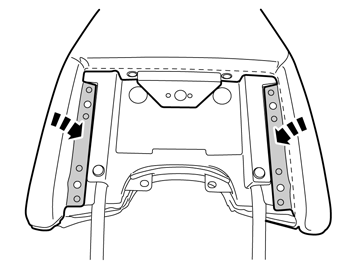
| | Applies to both seats Tape the cable harness on the cable tie. Tape as flat as possible. See image 22 B. Pull it up towards the upper edge of the seat and out through the hole for the headrest. Remove the cable tie and tape from the cable harness.
|
|  | | IMG-317224 |
|
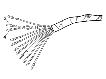
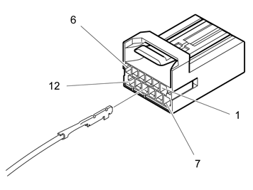
| | Caution!
There are two brown cables in the cable harness. The brown cable to terminal 4 is twinned with the blue cable to terminal 3. |
Position: Not connected. White (W) Blue (BL) Brown (BN) Red/White (R/W) Red (R) Black (SB) Brown (BN) Yellow (Y) Green (GN) Gray (GR) Pink (P)
|
|  | | IMG-317243 |
|
| | |
|  | | IMG-317244 |
|
| | |
|  | | IMG-262956 |
|
| | |
|  | | IMG-317245 |
|
| | |
|  | | IMG-317263 |
|
| | |
|  | | IMG-317325 |
|
| | |
|  | | IMG-317326 |
|
| | |
|  | | IMG-317327 |
|
| | Note!
The inward facing side in the car. |
|
|  | | IMG-317328 |
|
| | |
|  | | IMG-317329 |
|
| | |
|  | | IMG-317330 |
|
| | |
|  | | IMG-317331 |
|
| | |
|  | | IMG-317332 |
|
| | |
|  | | IMG-317333 |
|
| | Locate the hole under the upholstery on the headrest side, marked with tape. Make a hole in the upholstery using a scriber or an awl.
Note!
The inward facing side in the car. |
|
|  | | IMG-317334 |
|
| | |
|  | | IMG-317335 |
|
| | |
|  | | IMG-317336 |
|
| | |
|  | | IMG-317337 |
|
| | |
|  | | IMG-317338 |
|
| | |
|  | | IMG-263002 |
|
| | Applies to the right-hand front seat and cars without heated seats |
|  | | IMG-263003 |
|
| | Take the cable harness from the headrest and pull forward, in underneath the seat. Follow the cable harness for the seat belt buckle. Tighten the cable tie (1). Secure the cable using two cable ties (2).
|
|  | | IMG-263004 |
|
| | Applies to the right-hand front seat and cars with heated seats Take the cable harness from the headrest and pull forward, in underneath the seat. Follow the cable harness for the heating element. Secure the cable using three cable ties (1).
|
|  | | IMG-263005 |
|
| | Applies to the right-hand front seat |
|  | | IMG-263006 |
|
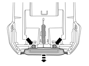
| | Take a piece of foam tape from the kit and cut it in the centre. Fold the seat forward slightly and connect the cable harness from the floor to the connector (1). Tape one cut piece of foam tape around the connectors. Place a cable tie on each side of the connectors and tighten. Check that the cable harness is not trapped when the seat is slid forwards and backwards.
The right-hand seat means the passenger seat Fold the backrest forward and backwards and check that the cable harness is not trapped when folding the backrest.
|
|  | | IMG-263009 |
|
| | Applies to the left-hand seat and cars without heated seats |
|  | | IMG-263010 |
|
| | Take the cable harness from the headrest and pull forward, underneath the seat. Follow the cable harness for the seat belt buckle. Tighten the cable tie (1). Secure the cable using two cable ties (2).
|
|  | | IMG-263011 |
|
| | Applies to the left-hand front seat and cars with heated seats Take the cable harness from the headrest and pull forward, in underneath the seat. Follow the cable harness for the heating element. Secure the cable using three cable ties (1).
|
|  | | IMG-263012 |
|
| | Applies to the left-hand front seat. Route the cable harness under the seat. Connect the cable harness from the floor to the connector (1). Secure it using a cable tie in the existing cable harness or in a bracket. Tape one cut piece of foam tape around the connectors. Place a cable tie on each side of the connectors and tighten. Check that the cable harness is not trapped when the seat is slid forwards and backwards.
The left-hand seat means the passenger seat Fold the backrest forward and backwards and check that the cable harness is not trapped when folding the backrest.
|
|  | | IMG-268416 |
|
| | |
|  | | IMG-268417 |
|
| | |
|  | | IMG-268418 |
|
| | |
|  | | IMG-268419 |
|
| | |
|  | | IMG-268444 |
|
| | |
|  | | IMG-268445 |
|
| | |
|  | | IMG-268446 |
|
| | |
|  | | IMG-268447 |
|
| | |
|  | | IMG-268448 |
|
| | |
|  | | IMG-268450 |
|
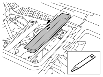
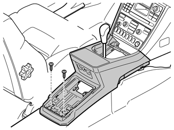
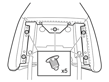
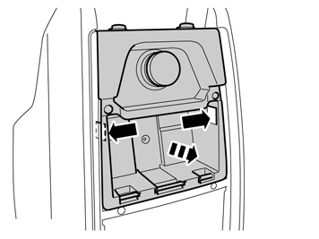
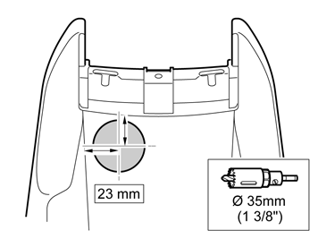
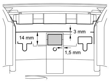
| | Mark as illustrated on the tunnel console's storage compartment. Pre-drill using a Ø 2.5 mm (3/32") bit. Drill out the hole. Use a Ø35 mm (1 3/8") diameter hole saw. Smooth off the hole edges.
|
|  | | IMG-268451 |
|
| | Points 65 - 66 apply when the tunnel console is not prepared for the RSE system |
|  | | IMG-268452 |
|
| | |
|  | | IMG-268453 |
|
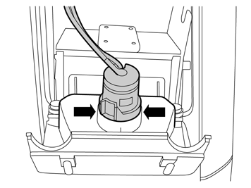
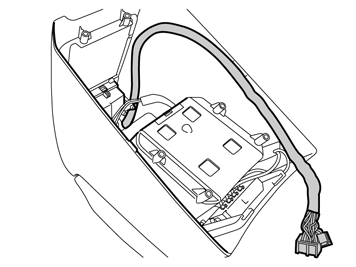
| | Applies to all models Take the lower section of the cover and cable harness (B) from the kit. Insert the end with the three (4 x with Digital TV receiver) connectors through the hole. Install the rubber grommet.
|
|  | | IMG-268454 |
|
| | |
|  | | IMG-268456 |
|
| | |
|  | | IMG-268457 |
|
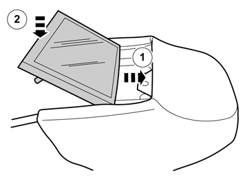
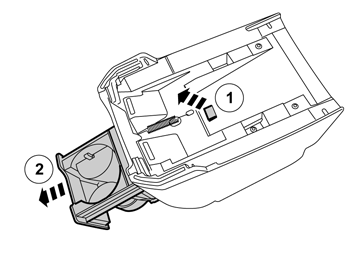
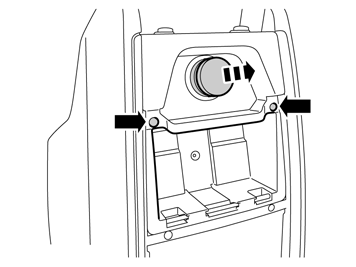
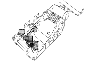
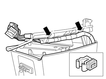
| | Place the DVD unit in the lower section of the cover as illustrated. Ensure that the cable harness goes under the DVD unit and does not protrude towards the open button or screw tower. Install the four screws and tighten.
|
|  | | IMG-268458 |
|
| | |
|  | | IMG-268467 |
|
| | |
|  | | IMG-268459 |
|
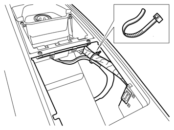
| | Route the cable harness in from the DVD unit through the drilled hole and down on the right-hand side of the tunnel console. Install the rubber grommet. Check that the rubber grommet's flanges are against the console.
|
|  | | IMG-268460 |
|
| | |
|  | | IMG-268464 |
|
| | |
|  | | IMG-268466 |
|
| | |
|  | | IMG-268468 |
|
| | |
|  | | IMG-268471 |
|
| | |
|  | | IMG-268472 |
|
| | |
|  | | IMG-268473 |
|
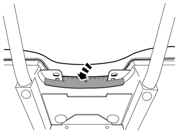
| | Open and close the cover three times. Check that the lock at the front edge works and that the rubber bushings are in place. The cable harness should be in a loop as illustrated.
|
|  | | IMG-268476 |
|
| | |
|  | | IMG-268487 |
|
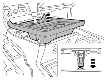
| | Thread the cable harness out through the square cut out on the lower section of the tunnel console. Secure the two clips of the cable harness on the plastic flanges. Tighten the lower section using the 6 screws.
|
|  | | IMG-268488 |
|
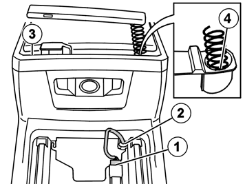
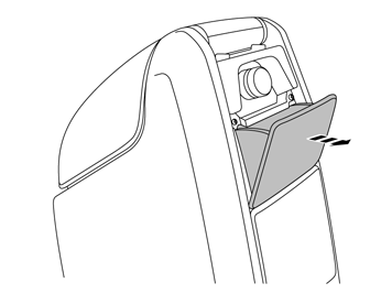
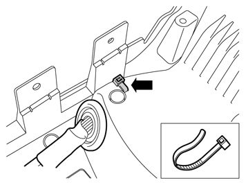
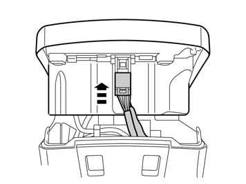
| | Take a cable tie and secure the 12V socket's cable by the clip on the cable harness from the DVD unit. The cable tie catch should point towards the outer side of the tunnel console. Reinstall the cup holder.
|
|  | | IMG-268489 |
|
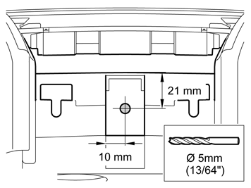
| | Make marks for drill holes on the opening handle for the tunnel console as illustrated. Pre-drill using a Ø 2.5 mm (3/32") bit. Drill out the hole using a Ø 6 mm ( 15/64") drill bit.
|
|  | | IMG-268490 |
|
| | Digital TV receivers must then be installed: Continue with the installation instructions: TV receiver, digital. |
|  | | IMG-268491 |
|
| | |
|  | | IMG-268492 |
|
| | |
|  | | IMG-268493 |
|
| | |
|  | | IMG-268494 |
|
| | |
|  | | IMG-268496 |
|
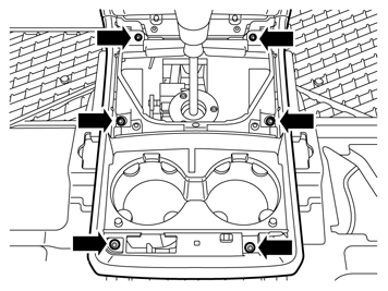
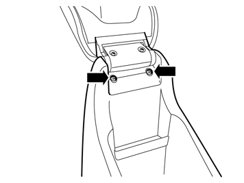
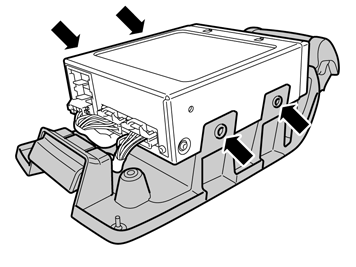
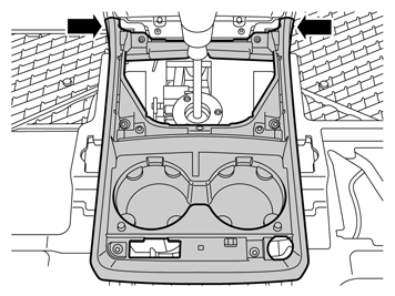
| | Install the tunnel console's upper panel. Check that the panel hooks securely at the front edge. Reinstall the tunnel console's 8 screws and tighten them.
|
|  | | IMG-268497 |
|
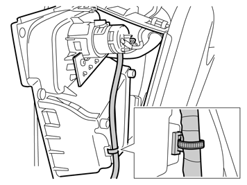
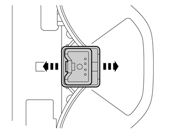
| | Applies to cars with telephone Reinstall the telephone cradle with the screws (3). Route the telephone cable. Install the telephone cable in the load-removing grommet (2). Connect the connector (1).
|
|  | | IMG-268498 |
|
| | |
|  | | IMG-268499 |
|
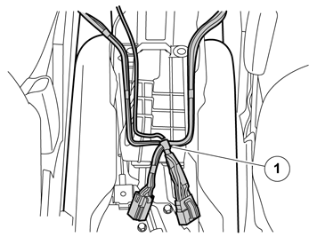
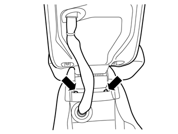
| | Take the rear tunnel console. Connect the two connectors for the RSE system (3 x with Digital TV-receiver.) Take two pieces of foam tape from the kit and wrap them around the connectors. Cut off the foam tape excess.
|
|  | | IMG-268500 |
|
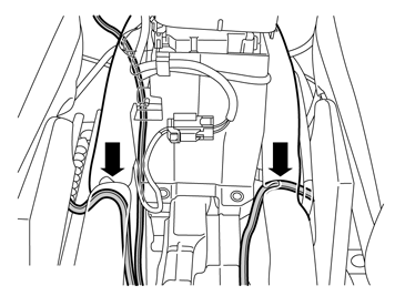
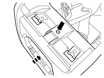
| | Insert the connectors into the tunnel console. Hook the connector on for the 12 V socket. Slide the rear tunnel console forwards in its grooves until it locks and check that the cable harness is not trapped.
|
|  | | IMG-268501 |
|
| | |
|  | | IMG-241303 |
|
| | Note!
The pre-routed connector is already connected on certain versions. |
|
|  | | IMG-268502 |
|
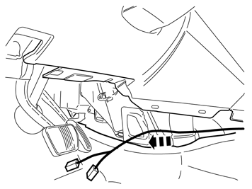
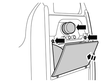
| | Connect the cable harness to the existing connector (1). Wrap a piece of foam tape around the connected connectors and cut off the excess. Install the connector (2) on the car's existing cable harness using a cable tie.
Note!
The pre-routed connector is already connected on certain versions. In such a case, disconnect it and connect both connectors from the new cable harness. Wrap a piece of foam tape around the connectors. |
|
|  | | IMG-275777 |
|
| | Install the batteries in the remote control and headsets. Region code the DVD player. Information is in VIDA under: Product specifications Design and Function 39 Media, communication and navigation 393 Equipment for entertainment Rear seat entertainment system Design
To activate the TV function Aim the remote control at the screen and press DAY/NIGHT ("on/off") for approx. 5 seconds until SERVICE MENU is displayed. Enter code 1971, press OK. Select SET TV, press OK. Select TV connected, press OK. Exit.
|
|  | | R8903555 |
|
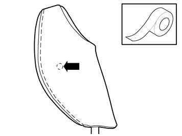
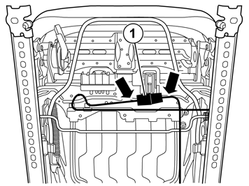
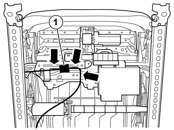
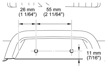
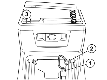
| | Installing decals (Only applies to USA and Canada) Take the black decal from the kit. Clean the area (1) where the decal will be located. Use a mixture of 30% windscreen washer fluid and 70% water. Wipe dry. Remove the backing paper from the adhesive side of the decal. Secure the decal as illustrated. Press the decal into place properly.
|