| | |
| | Read through all of the instructions before starting installation. Notifications and warning texts are for your safety and to minimise the risk of something breaking during installation. Ensure that all tools stated in the instructions are available before starting installation. Certain steps in the instructions are only presented in the form of images. Explanatory text is also given for more complicated steps. In the event of any problems with the instructions or the accessory, contact your local Volvo dealer.
|
| | |
|  | | IMG-400010 |
|
| | Note!
This colour chart displays (in colour print and electronic version) the importance of the different colours used in the images of the method steps. |
Used for focused component, the component with which you will do something. Used as extra colors when you need to show or differentiate additional parts. Used for attachments that are to be removed/installed. May be screws, clips, connectors, etc. Used when the component is not fully removed from the vehicle but only hung to the side. Used for standard tools and special tools. Used as background color for vehicle components. Used for accessory components.
|
| | |
|  | | IMG-490633 |
|
| | |
|  | | IMG-490470 |
|
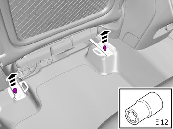
| | Adjust the seat to the front position. |
|  | | IMG-461960 |
|
| | Remove the screws.
Tightening torque: Front seat to body
, 40 Nm
|
|  | | IMG-490471 |
|
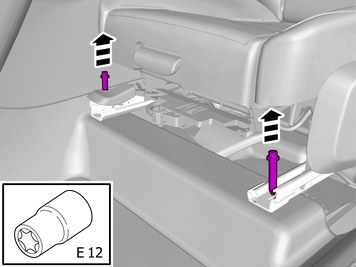
| | Adjust the seat to the rear position. |
|  | | IMG-461961 |
|
| | Remove the screws.
Tightening torque: Front seat to body
, 40 Nm
|
|  | | IMG-490472 |
|
| | |
| | Disconnecting the battery |
| 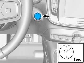 | | IMG-430215 |
|
| | |
|  | | IMG-480317 |
|
| | |
|  | | IMG-473728 |
|
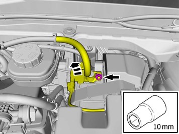
| | Remove the battery's negative cable.
Tightening torque: Battery cable for battery
, 6 Nm
|
| | |
|  | | IMG-490428 |
|
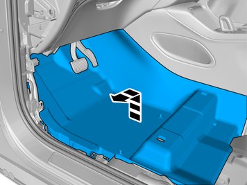
| | Note!
The graphic shows the back of the component before removal. |
|
|  | | IMG-490426 |
|
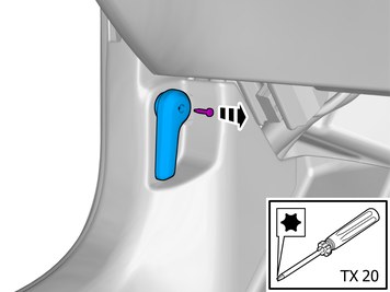
| | Remove the marked part. Use: Interior trim remover
|
|  | | IMG-490429 |
|
| | |
|  | | IMG-462002 |
|
| | Remove the screw. Remove the marked part. |
|  | | IMG-490482 |
|
| | |
|  | | IMG-461971 |
|
| | |
|  | | IMG-490581 |
|
| | Note!
The graphic shows the back of the component before removal. |
|
|  | | IMG-490582 |
|
| | |
|  | | IMG-490641 |
|
| | |
|  | | IMG-490642 |
|
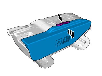
| | Remove the nuts. Loosen the component indicated. Do not remove it. |
|  | | IMG-490643 |
|
| | Release the lock. Remove the marked part. |
| | |
| | Vehicles without APMS (variant code MG01) |
|  | | IMG-491037 |
|
| | |
|  | | IMG-491710 |
|
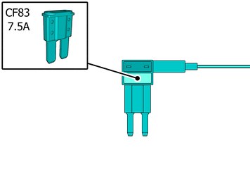
| | Use details according to image. Install component that comes with the accessory kit. |
|  | | IMG-491225 |
|
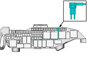
| | Install component that comes with the accessory kit. Position/route the cable as illustrated. |
| | Vehicles with APMS (variant code MG02) |
|  | | IMG-491036 |
|
| | |
|  | | IMG-491711 |
|
| | Use details according to image. Install component that comes with the accessory kit. |
|  | | IMG-491224 |
|
| | Install component that comes with the accessory kit. Position/route the cable as illustrated. |
| | Vehicles with Twin Engine / Recharge Plug-in Hybrid |
|  | | IMG-491219 |
|
| | Position/route the cable as illustrated. |
|  | | IMG-491024 |
|
| | Caution!
Make sure that no part of the wiring harness is trapped. |
Position/route the cable as illustrated. |
| | Applies to all other vehicles |
|  | | IMG-491218 |
|
| | Position/route the cable as illustrated. |
|  | | IMG-491025 |
|
| | Caution!
Make sure that no part of the wiring harness is trapped. |
Position/route the cable as illustrated. |
| | |
|  | | IMG-491370 |
|
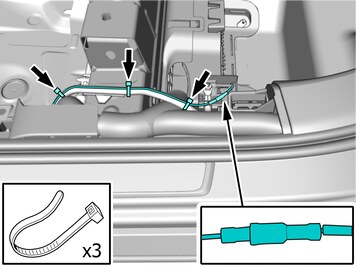
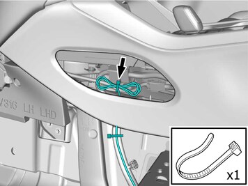
| | Connect the cable. Route the wires adjacent to existing wirings. Use a cable tie |
|  | | IMG-491686 |
|
| | |
|  | | IMG-490607 |
|
| | |
|  | | IMG-490609 |
|
| | Connect the prerouted cable. Install the nut.
Tightening torque: M6
, 10 Nm
|
|  | | IMG-490671 |
|
| | Route the wire adjacent to existing wirings. Use a cable tie |
|  | | IMG-490620 |
|
| | |
|  | | IMG-490657 |
|
| | Remove the clip. Remove the marked part. |
|  | | IMG-490621 |
|
| | Position/route the cable as illustrated. |
|  | | IMG-490728 |
|
| | Position/route the cable as illustrated. |
| | |
|  | | IMG-490342 |
|
| | |
|  | | IMG-490347 |
|
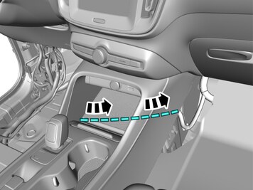
| | Loosen the marked details. |
| | |
|  | | IMG-490355 |
|
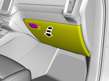
| | Release the locks. Remove the marked part. |
| | |
|  | | IMG-490371 |
|
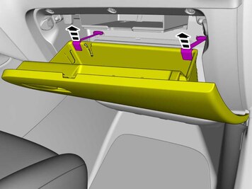
| | Release the locks. Open the lid. |
|  | | IMG-490372 |
|
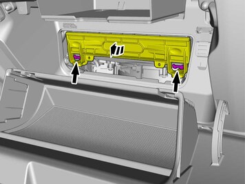
| | Remove the marked part. The part is not to be reused. |
| | |
|  | | IMG-491009 |
|
| | |
|  | | IMG-490376 |
|
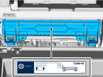
| | Install component that comes with the accessory kit. Place the template according to image |
|  | | IMG-490383 |
|
| | Make a hole, using the tool indicated. |
|  | | IMG-490986 |
|
| | Release the locks. Open the lid. |
|  | | IMG-491238 |
|
| | |
|  | | IMG-490994 |
|
| | Note!
Do not remove the protective film. |
Place the detail in position for installation. |
|  | | IMG-491008 |
|
| | Mark the centre. Use: Marker pen
|
|  | | IMG-491245 |
|
| | |
|  | | IMG-491254 |
|
| | Caution!
Cut carefully to avoid unintentional damage or personal injury. |
Measure and mark as illustrated. Make a hole, using the tool indicated. |
|  | | IMG-491255 |
|
| | Remove the protective film. Install the marked component. |
|  | | IMG-492956 |
|
| | Caution!
Sharp edge. Risk of injury. |
Caution!
Make sure that the components are positioned correctly. |
|
|  | | IMG-491661 |
|
| | |
|  | | IMG-491598 |
|
| | Install components that come with the accessory kit. |
|  | | IMG-491613 |
|
| | Pull the wiring through. Close the lid. |
|  | | IMG-491622 |
|
| | Install component that comes with the accessory kit. |
|  | | IMG-491685 |
|
| | Connect the prerouted cable. |
|  | | IMG-490734 |
|
| | Route the wire adjacent to existing wirings. |
|  | | IMG-490664 |
|
| | Install the cable. Use a cable tie |
|  | | IMG-490740 |
|
| | Position the cable harness excess as illustrated. Install the cable. Use: , Strip clamp
|
| | |
| | Reinstall the removed parts in reverse order. |