| | |
| | Read through all of the instructions before starting installation. Notifications and warning texts are for your safety and to minimise the risk of something breaking during installation. Ensure that all tools stated in the instructions are available before starting installation. Certain steps in the instructions are only presented in the form of images. Explanatory text is also given for more complicated steps. In the event of any problems with the instructions or the accessory, contact your local Volvo dealer.
|
| | |
|  | | IMG-400007 |
|
| | When installing, the car must retain a temperature of 20 degrees C. After installation, the car must not be washed for 48 hours |
| | |
|  | | IMG-363036 |
|
| | Note!
This colour chart displays (in colour print and electronic version) the importance of the different colours used in the images of the method steps. |
Used for focused component, the component with which you will do something. Used as extra colors when you need to show or differentiate additional parts. Used for attachments that are to be removed/installed. May be screws, clips, connectors, etc. Used when the component is not fully removed from the vehicle but only hung to the side. Used for standard tools and special tools. Used as background color for vehicle components.
|
| | |
|  | | IMG-350367 |
|
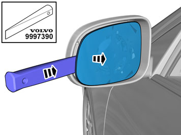
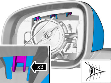
| | Caution!
Observe caution, the glass breaks easily. |
Remove the glass from the mirror. |
|  | | IMG-350369 |
|
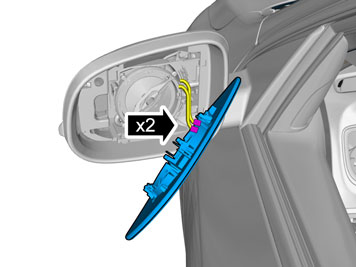
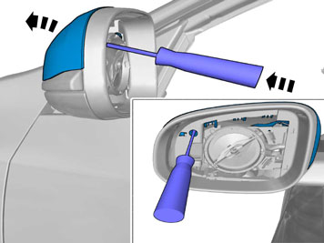
| | Disconnect the connectors. |
|  | | IMG-350368 |
|
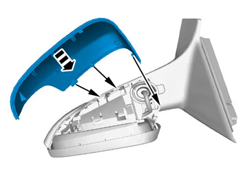
| | |
|  | | IMG-359036 |
|
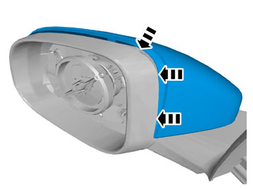
| | |
|  | | IMG-350370 |
|
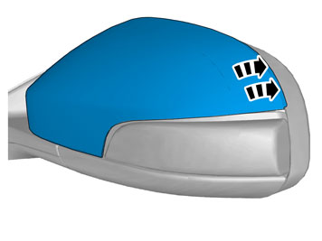
| | |
| | |
|  | | IMG-418627 |
|
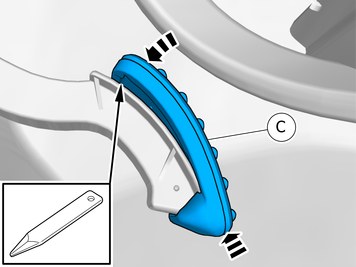
| | |
|  | | IMG-359046 |
|
| | |
|  | | IMG-359048 |
|
| | |
|  | | IMG-359047 |
|
| | |
| | Repeat all method steps for the other side. Reinstall the removed parts in reverse order. |
| | |
|  | | IMG-416296 |
|
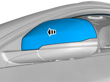
| | Remove the marked part. Use: Interior trim remover
|
| | |
|  | | IMG-416245 |
|
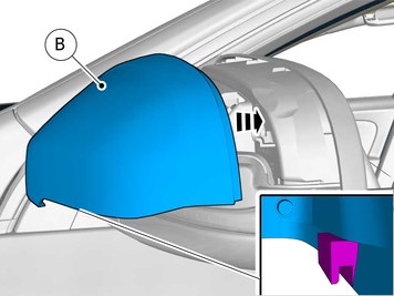
| | Install component that comes with the accessory kit. Use: Interior trim remover
|
|  | | IMG-416295 |
|
| | Install component that comes with the accessory kit. Use: Interior trim remover
|
|  | | IMG-416251 |
|
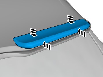
| | Place the component where indicated in the graphic. |
|  | | IMG-416252 |
|
| | |
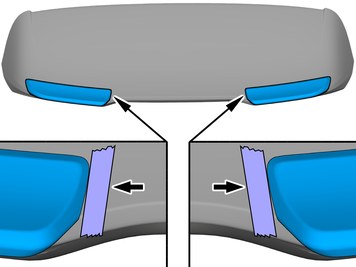
| | When installing on right-hand drive cars, perform the procedures on the opposite side and/or mirrored. |
| | |
|  | | IMG-414897 |
|
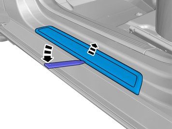
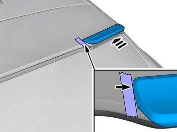
| | Remove the part carefully |
|  | | IMG-414896 |
|
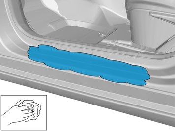
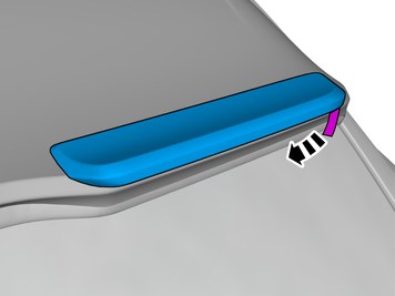
| | Clean the surface. Wipe dry. |
| | |
|  | | IMG-418630 |
|
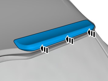
| | Remove the protective film. Install component that comes with the accessory kit. |
|  | | IMG-414899 |
|
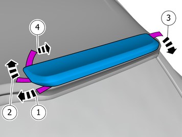
| | Note!
Press and apply pressure to the part over the tape for at least 20 seconds. |
|
| | Repeat all method steps for the other side. |
| | |
|  | | IMG-352899 |
|
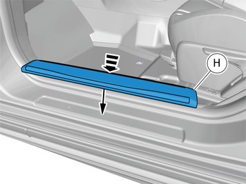
| | Remove the part carefully |
|  | | IMG-352929 |
|
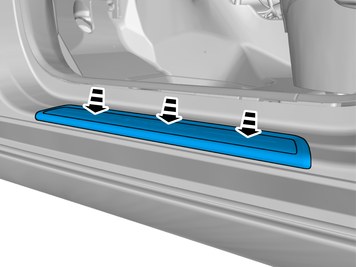
| | |
|  | | IMG-352977 |
|
| | |
|  | | IMG-368127 |
|
| | |
|  | | IMG-352821 |
|
| | |
|  | | IMG-352822 |
|
| | |
|  | | IMG-361980 |
|
| | |
|  | | IMG-356816 |
|
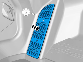
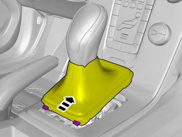
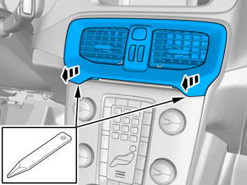
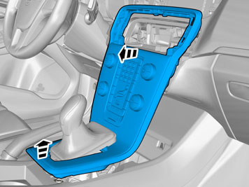
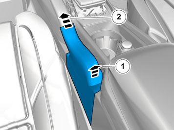
| | Remove the marked part. Use: Interior trim remover
|
|  | | IMG-352951 |
|
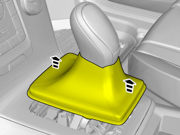
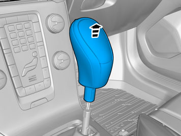
| | Disconnect the connector. |
|  | | IMG-352901 |
|
| | |
|  | | IMG-367797 |
|
| | |
|  | | IMG-367741 |
|
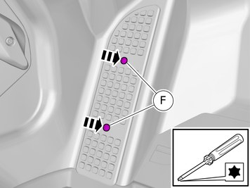
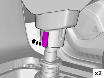
| | Release the lock. Repeat on the other side. Use: Electrician's screwdriver
|
|  | | IMG-367751 |
|
| | |
|  | | IMG-357001 |
|
| | |
|  | | IMG-357002 |
|
| | |
|  | | IMG-357011 |
|
| | |
|  | | IMG-368060 |
|
| | |
|  | | IMG-368062 |
|
| | |
|  | | IMG-368064 |
|
| | |
|  | | IMG-367755 |
|
| | |
|  | | IMG-368079 |
|
| | |
|  | | IMG-368209 |
|
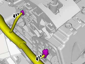
| | Note!
The number of connectors may vary depending on the vehicle's equipment level. |
Disconnect the connectors. |
|  | | IMG-368195 |
|
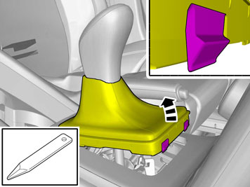
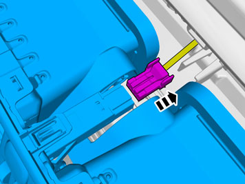
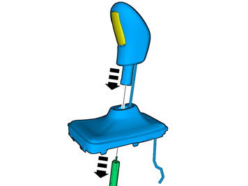
| | Depress the locking device. |
|  | | IMG-368226 |
|
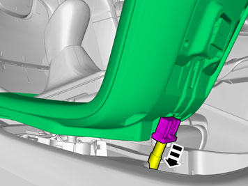
| | Release the gearshift cable. |
|  | | IMG-368203 |
|
| | |
|  | | IMG-368198 |
|
| | Release the gearshift cable. |
|  | | IMG-368178 |
|
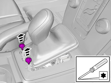
| | Remove the screws. Repeat on the other side. |
|  | | IMG-368227 |
|
| | |
| | |
|  | | IMG-418632 |
|
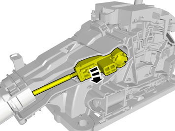
| | Caution!
Take extra care not to damage the wiring harnesses. |
Install component that comes with the accessory kit. Pull the wiring through. |
|  | | IMG-367926 |
|
| | |
|  | | IMG-367958 |
|
| | |
|  | | IMG-367983 |
|
| | |
|  | | IMG-368004 |
|
| | Caution!
Take extra care not to damage the wiring harnesses. |
|
|  | | IMG-368012 |
|
| | Caution!
Take extra care not to damage the wiring harnesses. |
A click confirms that the component is in the correct position. |
|  | | IMG-368015 |
|
| | Caution!
Make sure that no part of the wiring harness is trapped. |
A click confirms that the component is in the correct position. |
|  | | IMG-368259 |
|
| | Caution!
Take extra care not to damage the wiring harnesses. |
Pull the wiring through. |
|  | | IMG-368272 |
|
| | |
|  | | IMG-368270 |
|
| | Release the lock. Lift approximately 2 mm. Use: Electrician's screwdriver
|
|  | | IMG-368271 |
|
| | Caution!
Take extra care not to damage the wiring harnesses. |
Note the position. Connect the cable harness. Depress the locking device. |
| | Reinstall the removed parts in reverse order. |
| | |
|  | | IMG-411545 |
|
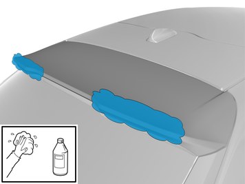
| | Clean the surfaces. Use: 1161721, Isopropanol
|
| | |
|  | | IMG-418640 |
|
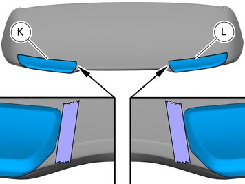
| | Note!
Make sure that the component is centred. |
Place the component where indicated in the graphic. Use appropriate tape to mark the position.
Use: , Masking tape
|
|  | | IMG-411447 |
|
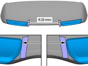
| | Measure Use: Tape measure
Remove the marked part. |
|  | | IMG-411466 |
|
| | Fold the protective film forward |
|  | | IMG-411465 |
|
| | |
|  | | IMG-411531 |
|
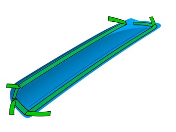
| | Caution!
Cut carefully to avoid unintentional damage or personal injury. |
Cut the component following the instructions in the graphic. |
|  | | IMG-411533 |
|
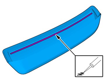
| | Apply the stated Material on the marked surface. Use: 8750060, Glue
|
|  | | IMG-411540 |
|
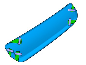
| | Note!
Make sure that the mating faces are clean and free of foreign material. |
Install component that comes with the accessory kit. Place the component where indicated in the graphic. |
|  | | IMG-411727 |
|
| | Remove the protective film. |
|  | | IMG-411735 |
|
| | Note!
Press and apply pressure to the part over the tape for at least 20 seconds. |
|
|  | | IMG-411541 |
|
| | Remove the protective film. |
|  | | IMG-411542 |
|
| | Note!
Press and apply pressure to the part over the tape for at least 20 seconds. |
|
| | Repeat the steps when installing accessories on opposite side. |
|  | | IMG-411543 |
|
| | |