| | |
|  | | IMG-363036 |
|
| | Color symbols Note!
This colour chart displays (in colour print and electronic version) the importance of the different colours used in the images of the method steps. |
Used for focused part, the part that you are to do something with. Used as extra colors when you need to show or differentiate additional parts. Used for attachments that are to be removed/installed. May be screws, clips, connectors, etc. Used when the component is not fully removed from the vehicle but only hung to the side. Used for standard tools and special tools. Used as background color for vehicle components.
|
|  | | IMG-337272 |
|
| | |
|  | | IMG-337277 |
|
| | |
|  | | IMG-337278 |
|
| | |
|  | | IMG-337279 |
|
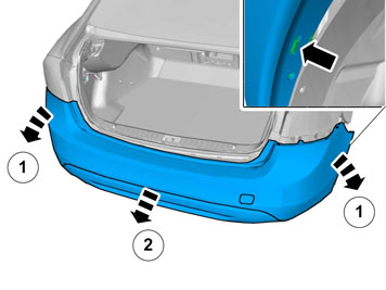
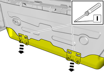
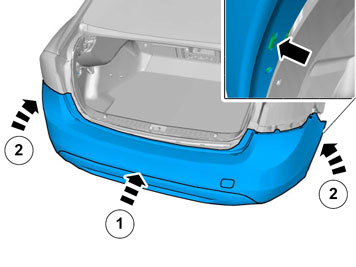
| | Note!
Two persons should perform the following work. |
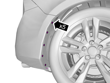
Unhook the end of the bumper cover at the front edge from the catches on both sides. Carefully pull off the ends of the bumper cover until the catches at the rear edge, at the rear fender and under the tail lamp, release. Pull the bumper cover backwards.
|
|  | | IMG-337311 |
|
| | |
|  | | IMG-337281 |
|
| | |
|  | | IMG-337283 |
|
| | |
|  | | IMG-337285 |
|
| | Applies to 4 and 6 cylinder engines |
|  | | IMG-337286 |
|
| | |
|  | | IMG-337287 |
|
| | |
|  | | IMG-337288 |
|
| | |
|  | | IMG-337289 |
|
| | |
|  | | IMG-337290 |
|
| | |
|  | | IMG-337291 |
|
| | |
|  | | IMG-337292 |
|
| | |
|  | | IMG-337293 |
|
| | |
|  | | IMG-338051 |
|
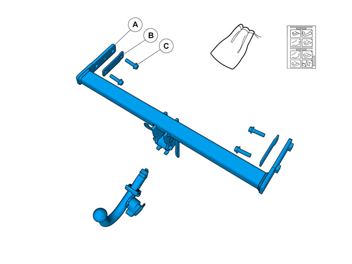
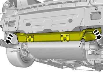
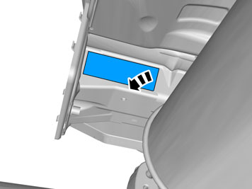
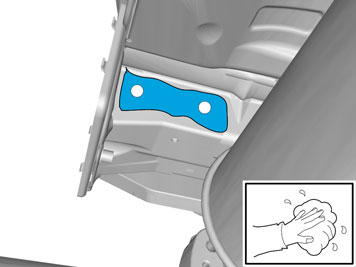
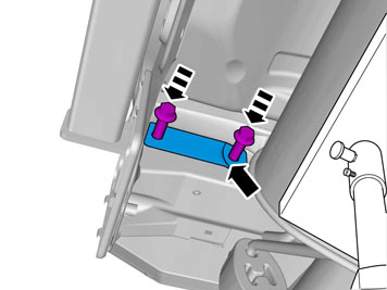
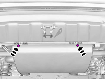
| | Accessory installation Check that the contact faces inside the side members are clean. If necessary, clean opposite where the towing member's side plates are to be fastened. Take the towing member from the kit and insert the two side plates in the holes at the rear edge of the side members.
|
|  | | IMG-337314 |
|
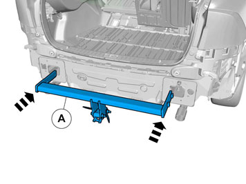
| | Note!
Do not damage the exhaust system. |
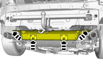
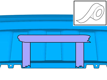
Note!
Ensure that the reinforcement bar is positioned correctly, with the embossed part pointing forward as illustrated. |
|
|  | | IMG-337317 |
|
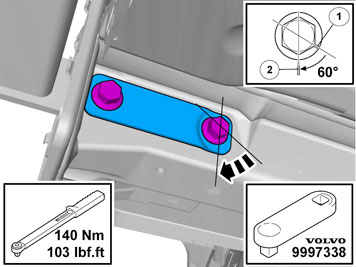
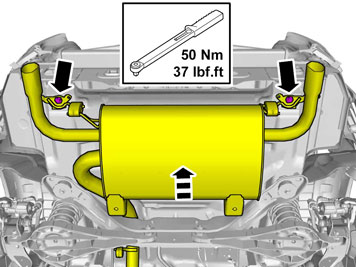
| | Tightening the screw joint Tighten the screws to 140 Nm (103 Ibf.ft.) and angle tighten to 60°. Use tool part no.9997338 to facilitate access. When angle tightening joints in confined areas a protractor cannot be placed on the torque wrench. Use the head of the hexagon bolt instead to determine the tightening angle. Use workshop lift part.no. 9985972 and fixture part.no. 9995972 under the silencer to position it for better access.
Mark the bolt head's flange (1). Make a second mark (2) in the side member or reinforcement bar. Tighten the screw so that the screw head marking (1) lines up with the marking (2) on the side member/reinforcement bar. Repeat for all screws.
|
|  | | IMG-374624 |
|
| | |
|  | | IMG-374625 |
|
| | |
|  | | IMG-338056 |
|
| | |
|  | | IMG-337297 |
|
| | |
|  | | IMG-337298 |
|
| | |
|  | | IMG-337299 |
|
| | |
|  | | IMG-337320 |
|
| | |
|  | | IMG-338568 |
|
| | |
|  | | IMG-357761 |
|
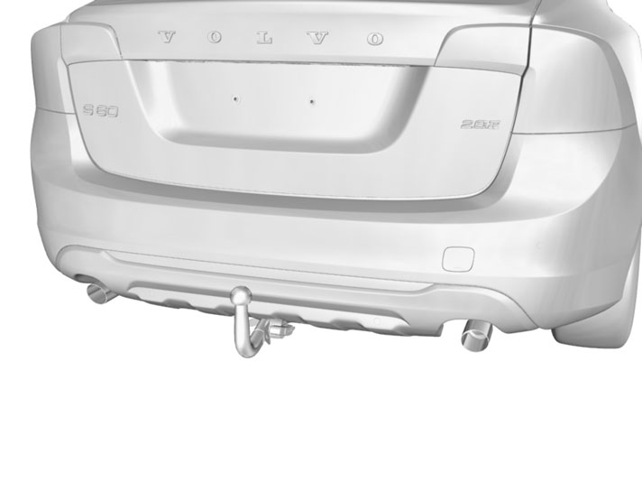
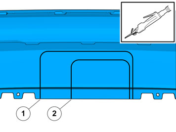
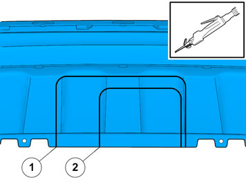
| | Applies to vehicles with standard spoiler 1. Marking for Detachable towbar 2. Marking for fixed towbar |
|  | | IMG-357792 |
|
| | Applies to vehicles with skid plate |
|  | | IMG-353440 |
|
| | 1 Marking for detachable towbar 2 Marking for fixed towbar |
|  | | IMG-357807 |
|
| | Applies to vehicles with R-design |
|  | | IMG-358397 |
|
| | Note!
Do not use existing lines in the bumper cover as a cut-out template for the detachable tow hitch R-design. Use the cut-out template supplied in the accessory kit. |
|
|  | | IMG-358216 |
|
| | Place the template in the bumper cover. Place the template with the cut-out radii against the bumper cover's radius. |
|  | | IMG-358217 |
|
| | |
|  | | IMG-358263 |
|
| | |
|  | | IMG-337324 |
|
| | Installation Applies to all vehicles Note!
This part should be performed by two persons. |
|
|  | | IMG-338572 |
|
| | |
| | | IMG-337277 |
|
| | |
| | | IMG-337278 |
|
| | |
|  | | IMG-338573 |
|
| | |
|  | | IMG-340091 |
|
| | |
|  | | IMG-338586 |
|
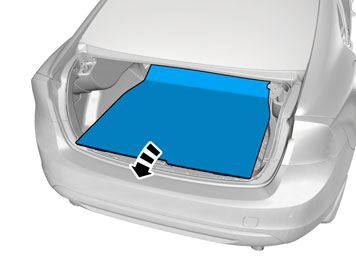
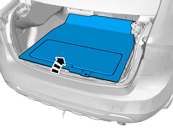
| | Applies to standard load floor |
|  | | IMG-338587 |
|
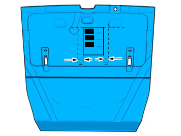
| | Applies to load floor with carrier bag holder |
|  | | IMG-338588 |
|
| | |
|  | | IMG-338589 |
|
| | |
|  | | IMG-338590 |
|
| | |
|  | | IMG-226909 |
|
| | |
|  | | IMG-227105 |
|
| | Press the protective casing into the holder until it is in contact with the bumper cover. A number of clicks must be heard when the protective casing is pressed in. Check that the protective casing is fitted securely.
|
|  | | IMG-226910 |
|
| | |