| | |
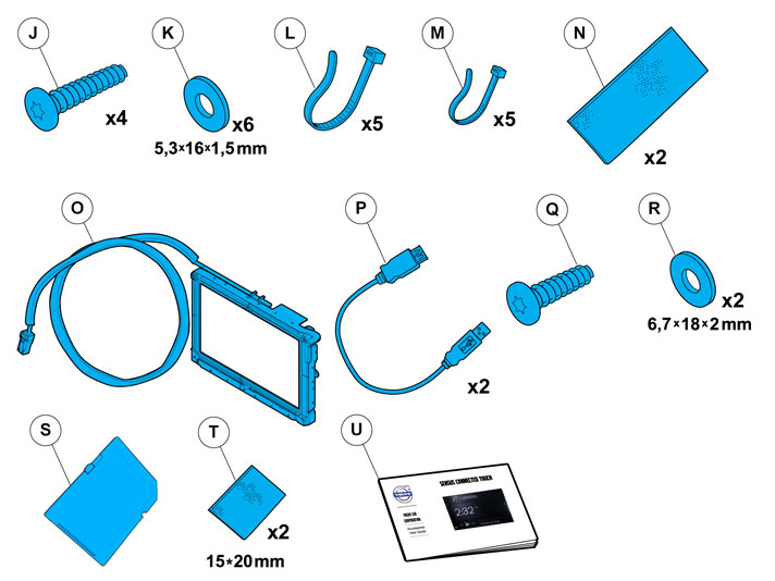
| | Read through all of the instructions before starting installation. Notifications and warning texts are for your safety and to minimise the risk of something breaking during installation. Ensure that all tools stated in the instructions are available before starting installation. Certain steps in the instructions are only presented in the form of images. Explanatory text is also given for more complicated steps. In the event of any problems with the instructions or the accessory, contact your local Volvo dealer.
|
| | |
| | These installation instructions show installation on left hand drive cars. When installing on right-hand drive cars, perform the procedures on the opposite side and/or mirrored. Where the procedure differs, the right-hand version is also shown with text and image. |
| | |
|  | | IMG-363036 |
|
| | Note!
This colour chart displays (in colour print and electronic version) the importance of the different colours used in the images of the method steps. |
Used for focused component, the component with which you will do something. Used as extra colors when you need to show or differentiate additional parts. Used for attachments that are to be removed/installed. May be screws, clips, connectors, etc. Used when the component is not fully removed from the vehicle but only hung to the side. Used for standard tools and special tools. Used as background color for vehicle components.
|
| | |
|  | | IMG-376633 |
|
| | |
|  | | IMG-376632 |
|
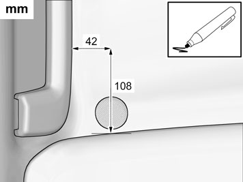
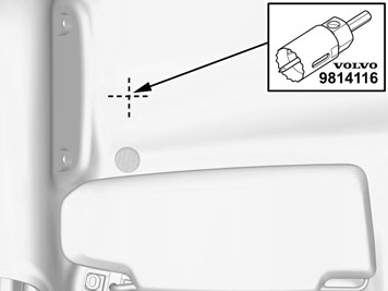
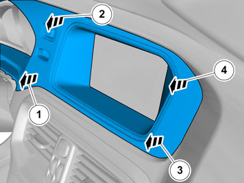
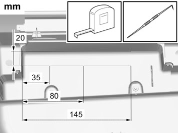
| | Measure and mark as illustrated. |
| | |
| | Note!
The removal steps may contain installation details. |
|
|  | | IMG-332193 |
|
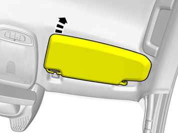
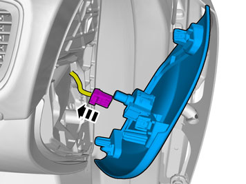
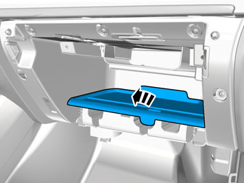
| | Set the ignition key to position 0. |
|  | | IMG-368711 |
|
| | |
|  | | IMG-368710 |
|
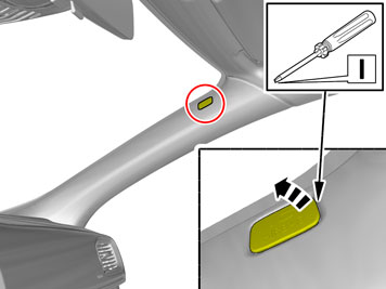
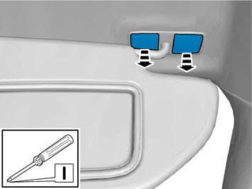
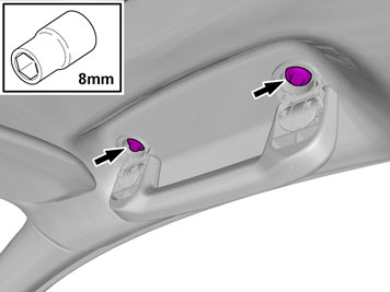
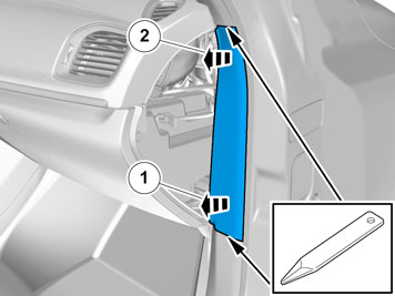
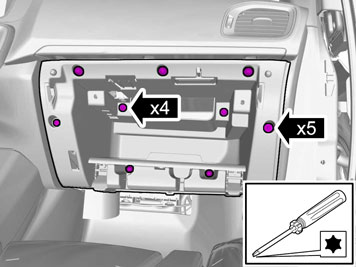
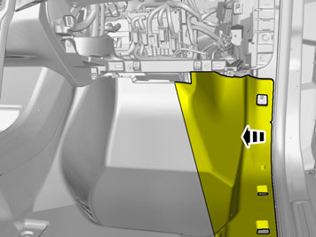
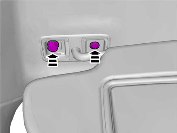
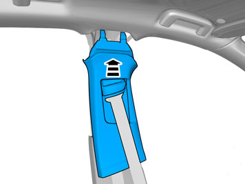
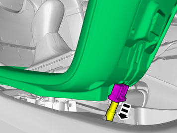
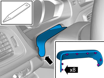
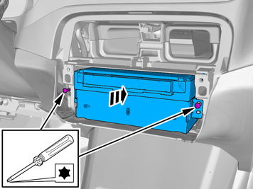
| | Remove the screw.
Tightening torque: Panel A-pillar
, 3 Nm
|
|  | | IMG-368709 |
|
| | |
|  | | IMG-376635 |
|
| | |
|  | | IMG-308358 |
|
| | |
|  | | IMG-346246 |
|
| | |
|  | | IMG-346247 |
|
| | |
|  | | IMG-375022 |
|
| | |
|  | | IMG-375023 |
|
| | |
|  | | IMG-375024 |
|
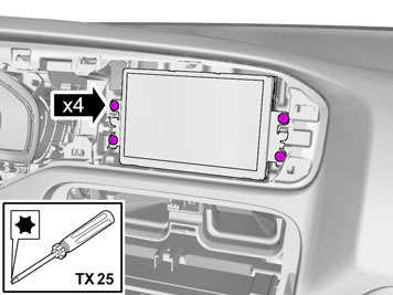
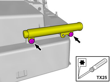
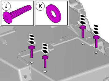
| | Remove the screws.
Tightening torque: M6
, 10 Nm
|
|  | | IMG-377070 |
|
| | Repeat the steps when removing on opposite side. |
|  | | IMG-376439 |
|
| | |
|  | | IMG-376636 |
|
| | Remove the weatherstrips. |
|  | | IMG-376638 |
|
| | |
|  | | IMG-376639 |
|
| | |
|  | | IMG-376308 |
|
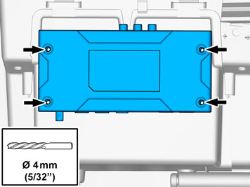
| | Remove the screws.
Tightening torque: M6
, 10 Nm
|
|  | | IMG-368766 |
|
| | |
|  | | IMG-378315 |
|
| | |
|  | | IMG-368768 |
|
| | |
|  | | IMG-368771 |
|
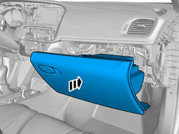
| | Caution!
Be extra careful when removing or installing this component. |
|
|  | | IMG-356946 |
|
| | |
|  | | IMG-356947 |
|
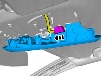
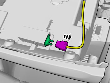
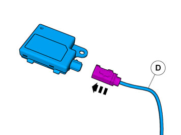
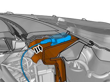
| | Disconnect the connector, if applicable. |
|  | | IMG-358478 |
|
| | |
|  | | IMG-358482 |
|
| | |
|  | | IMG-356817 |
|
| | |
|  | | IMG-368301 |
|
| | |
|  | | IMG-356822 |
|
| | |
|  | | IMG-356862 |
|
| | |
|  | | IMG-356868 |
|
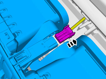
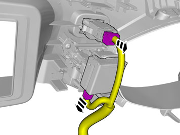
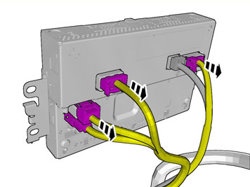
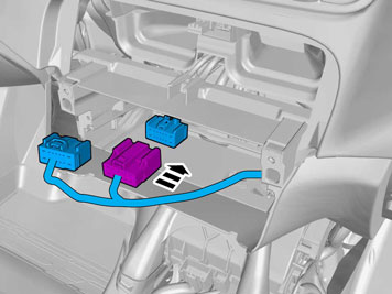
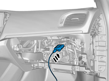
| | Disconnect the connector. |
|  | | IMG-356861 |
|
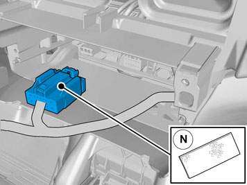
| | Disconnect the connector. |
|  | | IMG-376648 |
|
| | |
| | |
|  | | IMG-378343 |
|
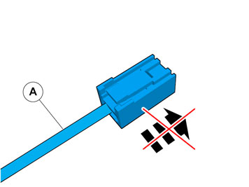
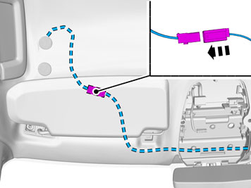
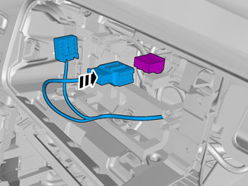
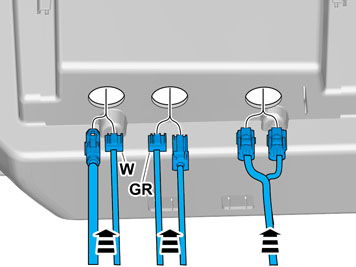
| | Caution!
Do not pull the connector when installing the wiring. |
|
|  | | IMG-376660 |
|
| | |
|  | | IMG-376659 |
|
| | |
|  | | IMG-376688 |
|
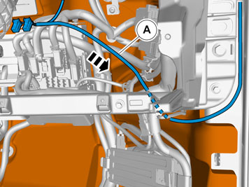
| | Caution!
Do not pull the connector when installing the wiring. |
|
|  | | IMG-376692 |
|
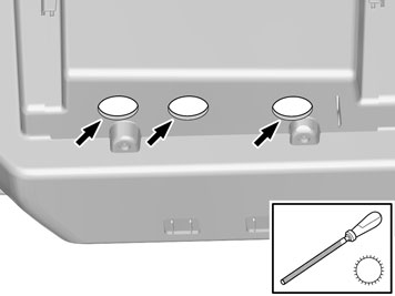
| | Caution!
Ensure that the roof is not damaged. |
Caution!
Take extra care not to crease the headliner. |
Use special tool: T9814116, Cylindrical knife
|
|  | | IMG-376694 |
|
| | |
|  | | IMG-376697 |
|
| | |
|  | | IMG-375489 |
|
| | Note!
Make sure that the direction arrow points towards the driver. |
|
|  | | IMG-375274 |
|
| | |
|  | | IMG-376698 |
|
| | |
|  | | IMG-376038 |
|
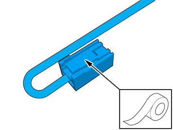
| | Turn once. Tear off the excess foam tape. |
|  | | IMG-376702 |
|
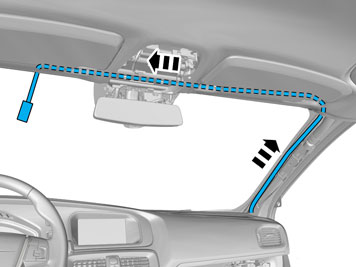
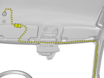
| | Adjust the position of the wiring harness. |
| | |
|  | | IMG-326818 |
|
| | |
|  | | IMG-326819 |
|
| | |
|  | | IMG-376302 |
|
| | |
|  | | IMG-303724 |
|
| | |
|  | | IMG-303744 |
|
| | |
| | Repeat the steps when installing on opposite side. |
|  | | IMG-376662 |
|
| | |
|  | | IMG-369490 |
|
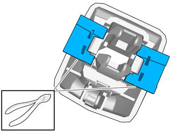
| | Caution!
Be careful not to damage the catches. |
|
|  | | IMG-369489 |
|
| | |
|  | | IMG-378368 |
|
| | |
|  | | IMG-378303 |
|
| | |
|  | | IMG-376709 |
|
| | |
|  | | IMG-376706 |
|
| | |
| | |
|  | | IMG-368127 |
|
| | |
|  | | IMG-352821 |
|
| | |
|  | | IMG-352822 |
|
| | Disconnect the connector. |
|  | | IMG-361980 |
|
| | |
|  | | IMG-356816 |
|
| | |
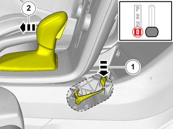
| | Cars with automatic transmissions |
|  | | IMG-369570 |
|
| | Release the shift-lock function. |
| | |
|  | | IMG-352899 |
|
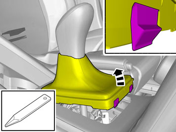
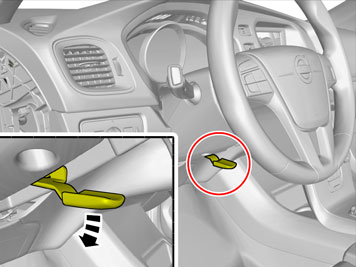
| | Remove the part carefully |
|  | | IMG-352929 |
|
| | |
|  | | IMG-352977 |
|
| | |
|  | | IMG-352951 |
|
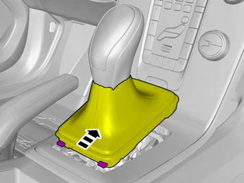
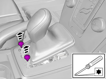
| | Detach the panel. Disconnect the connector. |
|  | | IMG-352901 |
|
| | |
|  | | IMG-368163 |
|
| | |
| | |
|  | | IMG-378370 |
|
| | |
|  | | IMG-375072 |
|
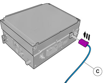
| | Disconnect the connector. |
|  | | IMG-378314 |
|
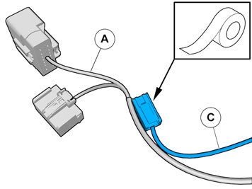
| | Attach the connector to the wiring harness. Use: , Electrical tape
The connector is not to be used. |
| | |
|  | | IMG-375073 |
|
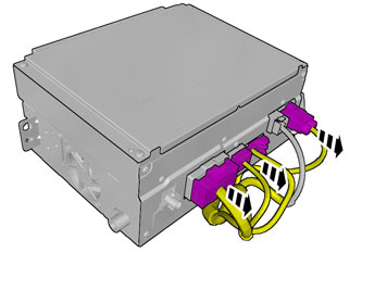
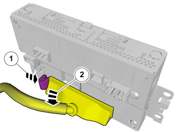
| | Note!
The number of connectors may vary depending on the vehicle's equipment level. |
Disconnect the connectors. |
|  | | IMG-361756 |
|
| | |
|  | | IMG-361757 |
|
| | |
|  | | IMG-368346 |
|
| | |
|  | | IMG-352828 |
|
| | |
|  | | IMG-371226 |
|
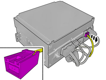
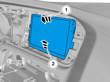
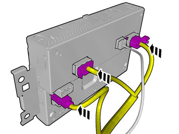
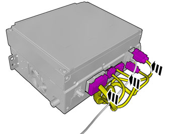
| | Note!
The graphic shows the back of the component before removal. |
|
|  | | IMG-371229 |
|
| | |
|  | | IMG-371228 |
|
| | |
|  | | IMG-367433 |
|
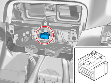
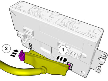
| | Disconnect the connectors. |
|  | | IMG-379244 |
|
| | |
|  | | IMG-378354 |
|
| | |
|  | | IMG-383559 |
|
| | |
|  | | IMG-375078 |
|
| | Disconnect the connector. |
| | | IMG-378314 |
|
| | Attach the connector to the wiring harness. Use: , Electrical tape
The connector is not to be used. |
|  | | IMG-375077 |
|
| | Note!
The number of connectors may vary depending on the vehicle's equipment level. |
Disconnect the connectors. |
|  | | IMG-356461 |
|
| | |
| | |
|  | | IMG-378006 |
|
| | |
|  | | IMG-378008 |
|
| | Caution!
Cut all the way to the radius. |
|
|  | | IMG-376721 |
|
| | |
|  | | IMG-378972 |
|
| | |
|  | | IMG-378973 |
|
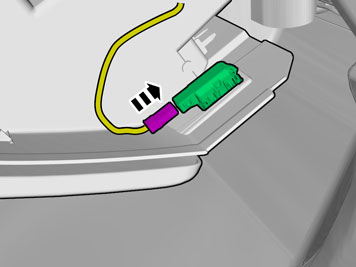
| | Connect the cable harness. |
|  | | IMG-378300 |
|
| | Turn once. Tear off the excess foam tape. |
|  | | IMG-378974 |
|
| | |
|  | | IMG-375616 |
|
| | Connect the cable harness. |
|  | | IMG-375609 |
|
| | Turn once. Tear off the excess foam tape. |
|  | | IMG-376739 |
|
| | |
|  | | IMG-376744 |
|
| | |
|  | | IMG-378918 |
|
| | Note!
This step requires considerable force. |
|
|  | | IMG-376806 |
|
| | |
|  | | IMG-378307 |
|
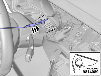
| |
Use special tool: T9814089, Anti-static strap
|
|  | | IMG-376807 |
|
| | |
|  | | IMG-375326 |
|
| | |
|  | | IMG-378791 |
|
| | |
|  | | IMG-376839 |
|
| | |
|  | | IMG-376840 |
|
| | |
| | |
|  | | IMG-375494 |
|
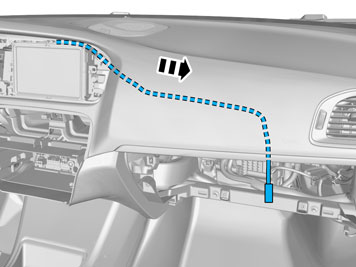
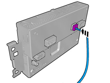
| | Connect the prerouted cable. |
|  | | IMG-375496 |
|
| | |
|  | | IMG-369406 |
|
| | |
|  | | IMG-378352 |
|
| | |
|  | | IMG-378428 |
|
| | |
|  | | IMG-378309 |
|
| | |
|  | | IMG-379256 |
|
| | Caution!
Make sure that no part of the wiring harness is trapped. |
Connect the connectors. Reinstall the removed part. |
|  | | IMG-378308 |
|
| | |
| | |
| | | IMG-378370 |
|
| | |
|  | | IMG-370448 |
|
| | Connect the prerouted cable. |
| | Vehicles without DVD-player |
|  | | IMG-378371 |
|
| | |
|  | | IMG-378373 |
|
| | Attach the connector to the wiring harness. Use: , Electrical tape
The connector is not to be used. |
| | |
|  | | IMG-370449 |
|
| | |
|  | | IMG-371174 |
|
| | |
| | |
|  | | IMG-378171 |
|
| | |
|  | | IMG-378959 |
|
| | Clean the surface. Use: , Isopropanol
|
|  | | IMG-378958 |
|
| | Note!
Ensure that the tape is fixed to the surface. |
|
|  | | IMG-375417 |
|
| | |
|  | | IMG-378173 |
|
| | Remove the protective film. |
|  | | IMG-376853 |
|
| | |
|  | | IMG-378970 |
|
| | |
|  | | IMG-378971 |
|
| | |
|  | | IMG-378969 |
|
| | |
|  | | IMG-376984 |
|
| | |
|  | | IMG-376985 |
|
| | |
|  | | IMG-376986 |
|
| | |
|  | | IMG-376987 |
|
| | |
|  | | IMG-376988 |
|
| | |
|  | | IMG-376989 |
|
| | Measure and mark as illustrated. |
|  | | IMG-376990 |
|
| | |
|  | | IMG-376991 |
|
| | |
| | | IMG-376988 |
|
| | |
|  | | IMG-375415 |
|
| | |
|  | | IMG-376992 |
|
| | |
|  | | IMG-375201 |
|
| | |
|  | | IMG-376993 |
|
| | |
|  | | IMG-370057 |
|
| | |
|  | | IMG-370059 |
|
| | |
|  | | IMG-370056 |
|
| | |
|  | | IMG-370035 |
|
| | Reinstall the removed part. |
| | | IMG-377070 |
|
| | Reinstall the removed parts in reverse order. |
|  | | IMG-242268 |
|
| | Download software (application) for the accessory's function according to the service information in VIDA. Order and download software according to: 31399196
|
|  | | IMG-378941 |
|
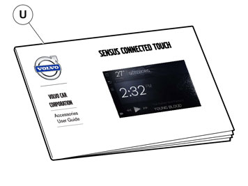
| | Place the manual for this accessory in a suitable location in the car. |
| | |
|  | | IMG-375960 |
|
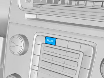
| | Turn on the ignition. Press the button marked "Media". Choose Sensus Connected Touch in the menu. Reply YES to the question "DO YOU ALLOW THE GPS POSITIONING DATA TO BE USED?" The Sensus Connected Touch start menu should show. Move your finger from right to left over the display. Start from the inner edge of the display. A new menu should now show. Turn off the ignition.
|
| | |
| | | IMG-377070 |
|
| | Follow the instructions on www.volvocars.com/sct-update and check if the system is equipped with the latest software. If not, follow the instructions to carry out update. |
| | Applies when the customer has chosen map information for navigation |
| | |
| | Does not apply to vehicles for the Chinese market. |
|  | | IMG-378291 |
|
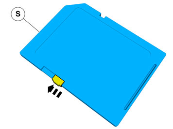
| | The part is not to be reused. |
| | |
| | |
|  | | IMG-378288 |
|
| | |
|  | | IMG-378292 |
|
| | |