| | |
| | Read through all of the instructions before starting installation. Notifications and warning texts are for your safety and to minimise the risk of something breaking during installation. Ensure that all tools stated in the instructions are available before starting installation. Certain steps in the instructions are only presented in the form of images. Explanatory text is also given for more complicated steps. In the event of any problems with the instructions or the accessory, contact your local Volvo dealer.
|
| | |
| | These installation instructions show installation on left hand drive cars. When installing on right-hand drive cars, perform the procedures on the opposite side and/or mirrored. Where the procedure differs, the right-hand version is also shown with text and image. When installing, the car must retain a temperature of 20 degrees C. Place the manual for this accessory in a suitable location in the car. |
| | |
|  | | IMG-363036 |
|
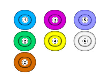
| | Note!
This colour chart displays (in colour print and electronic version) the importance of the different colours used in the images of the method steps. |
Used for focused component, the component with which you will do something. Used as extra colors when you need to show or differentiate additional parts. Used for attachments that are to be removed/installed. May be screws, clips, connectors, etc. Used when the component is not fully removed from the vehicle but only hung to the side. Used for standard tools and special tools. Used as background color for vehicle components.
|
| | |
| | |
|  | | IMG-355358 |
|
| | |
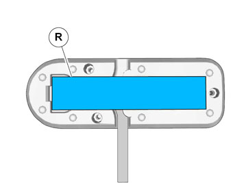
|  | | IMG-354904 |
|
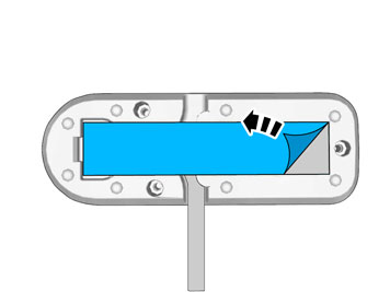
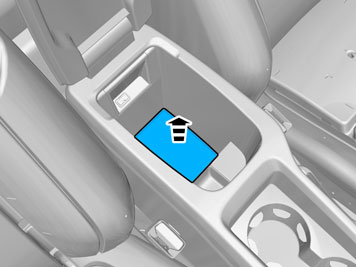
| | Remove the protective film. |
|  | | IMG-354905 |
|
| | |
| | Right-hand drive vehicles |
|  | | IMG-355357 |
|
| | |
| | | IMG-354904 |
|
| | Remove the protective film. |
|  | | IMG-354906 |
|
| | |
| | |
|  | | IMG-355071 |
|
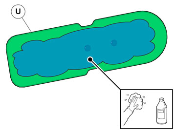
| | Clean the surface. Use: 1161721, Isopropanol
|
|  | | IMG-367458 |
|
| | Clean the surface. Use: 1161721, Isopropanol
|
|  | | IMG-356132 |
|
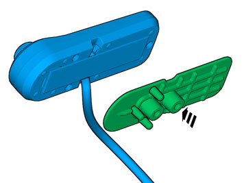
| | Install component that comes with the accessory kit. |
|  | | IMG-355074 |
|
| | Remove the protective film. |
|  | | IMG-367439 |
|
| | |
|  | | IMG-367469 |
|
| | |
| | |
|  | | IMG-332193 |
|
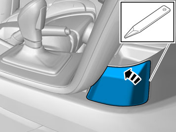
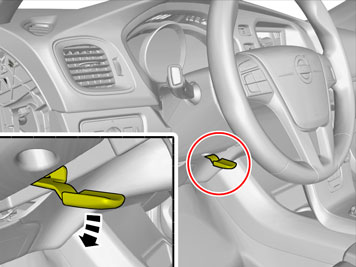
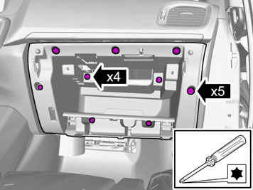
| | Set the ignition key to position 0. |
|  | | IMG-368127 |
|
| | |
|  | | IMG-352821 |
|
| | |
|  | | IMG-352822 |
|
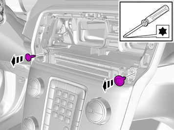
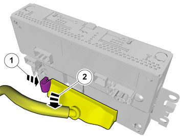
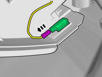
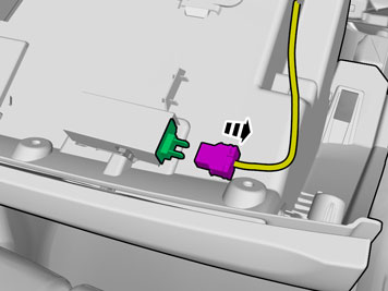
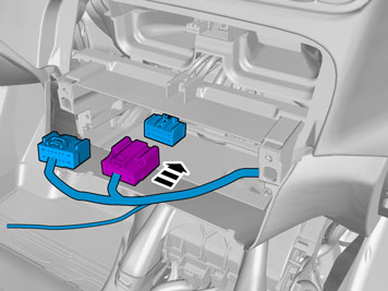
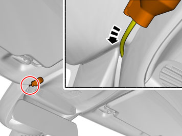
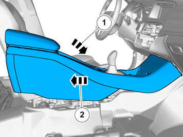
| | Disconnect the connector. |
|  | | IMG-361980 |
|
| | |
|  | | IMG-352899 |
|
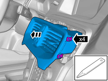
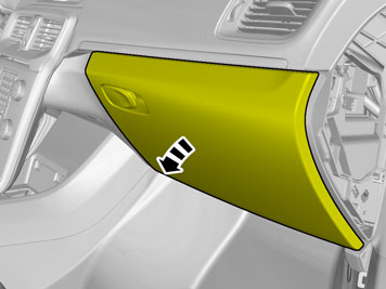
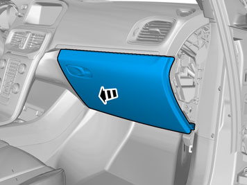
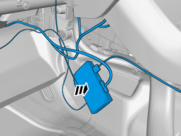
| | Remove the part carefully |
|  | | IMG-352929 |
|
| | |
|  | | IMG-352977 |
|
| | |
|  | | IMG-356816 |
|
| | |
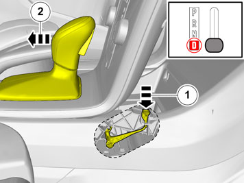
| | Cars with automatic transmissions |
|  | | IMG-369570 |
|
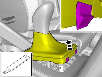
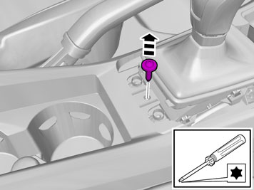
| | Release the shift-lock function. |
| | |
|  | | IMG-352951 |
|
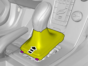
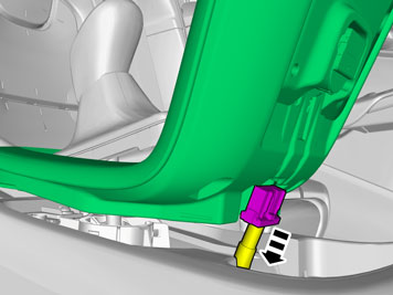
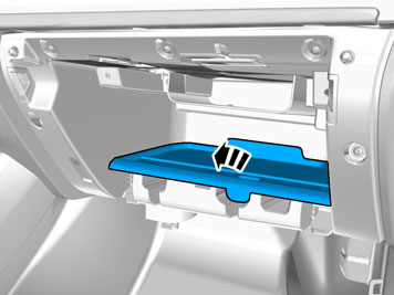
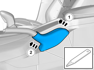
| | Detach the panel. Disconnect the connector. |
|  | | IMG-352901 |
|
| | |
|  | | IMG-368163 |
|
| | |
|  | | IMG-357021 |
|
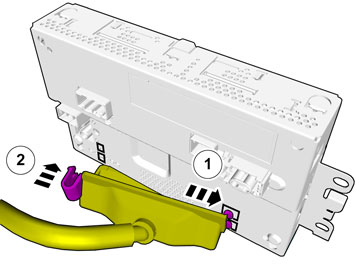
| | Disconnect the connectors. |
|  | | IMG-361756 |
|
| | |
|  | | IMG-361757 |
|
| | |
|  | | IMG-368346 |
|
| | |
|  | | IMG-352828 |
|
| | |
|  | | IMG-371226 |
|
| | |
|  | | IMG-371229 |
|
| | |
|  | | IMG-371228 |
|
| | |
|  | | IMG-367433 |
|
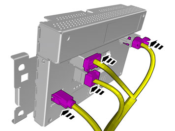
| | Disconnect the connectors. |
|  | | IMG-368177 |
|
| | |
|  | | IMG-346175 |
|
| | Disconnect the connectors. |
|  | | IMG-356461 |
|
| | |
|  | | IMG-356817 |
|
| | |
|  | | IMG-368301 |
|
| | |
|  | | IMG-356822 |
|
| | |
|  | | IMG-356862 |
|
| | |
|  | | IMG-356868 |
|
| | Disconnect the connector. |
|  | | IMG-356861 |
|
| | Disconnect the connector. |
|  | | IMG-361985 |
|
| | |
|  | | IMG-361967 |
|
| | |
|  | | IMG-361966 |
|
| | |
|  | | IMG-368064 |
|
| | |
|  | | IMG-357001 |
|
| | |
|  | | IMG-357002 |
|
| | |
|  | | IMG-357011 |
|
| | |
| | Cars with automatic transmissions |
|  | | IMG-369569 |
|
| | |
| | Cars with manual transmissions |
|  | | IMG-369528 |
|
| | |
| | |
|  | | IMG-368079 |
|
| | |
|  | | IMG-368151 |
|
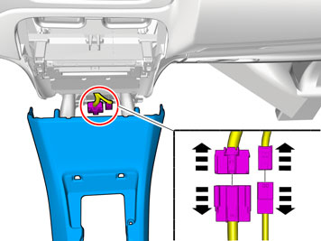
| | Disconnect the connectors. |
|  | | IMG-370141 |
|
| | |
| | |
|  | | IMG-369789 |
|
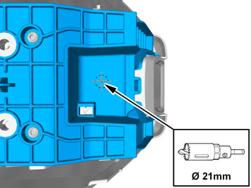
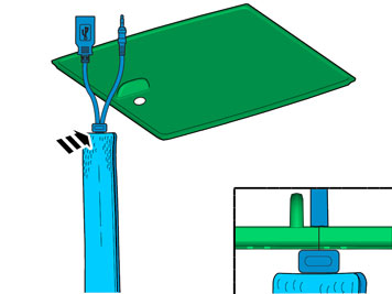
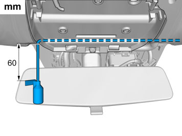
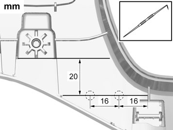
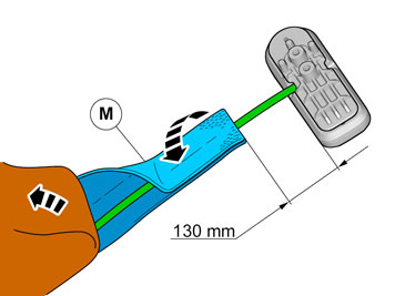
| | Measure and mark as illustrated. |
|  | | IMG-369793 |
|
| | |
|  | | IMG-369795 |
|
| | Measure and mark as illustrated. |
|  | | IMG-369799 |
|
| | |
|  | | IMG-369800 |
|
| | |
|  | | IMG-368860 |
|
| | |
|  | | IMG-368848 |
|
| | |
|  | | IMG-368849 |
|
| | |
|  | | IMG-369815 |
|
| | |
|  | | IMG-369820 |
|
| | |
|  | | IMG-369831 |
|
| | |
|  | | IMG-355451 |
|
| | |
| | |
|  | | IMG-369838 |
|
| | |
| | Right-hand drive vehicles |
|  | | IMG-369839 |
|
| | |
|  | | IMG-369847 |
|
| | |
| | |
|  | | IMG-369885 |
|
| | |
|  | | IMG-369884 |
|
| | |
|  | | IMG-369883 |
|
| | Connect the cable harness. |
|  | | IMG-369882 |
|
| | Tear off the excess foam tape. |
|  | | IMG-370139 |
|
| | |
|  | | IMG-369886 |
|
| | |
|  | | IMG-343541 |
|
| | Release the connector's secondary lock. Lift approximately 2 mm. |
|  | | IMG-341005 |
|
| | Connect the cable harness. Depress the secondary lock. |
| | |
|  | | IMG-369406 |
|
| | |
|  | | IMG-370075 |
|
| | |
|  | | IMG-369936 |
|
| | |
| | |
|  | | IMG-356946 |
|
| | |
|  | | IMG-356947 |
|
| | Disconnect the connector, if applicable. |
|  | | IMG-358478 |
|
| | |
|  | | IMG-358482 |
|
| | |
|  | | IMG-368711 |
|
| | |
|  | | IMG-368710 |
|
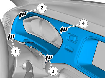
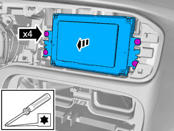
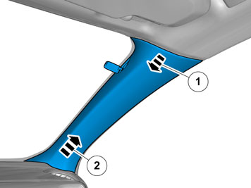
| | Remove the screw.
Tightening torque: Panel A-pillar
, 3 Nm
|
|  | | IMG-368709 |
|
| | |
|  | | IMG-368766 |
|
| | |
|  | | IMG-368768 |
|
| | |
|  | | IMG-368771 |
|
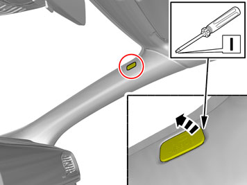
| | Caution!
Be extra careful when removing or installing this component. |
|
| | |
|  | | IMG-368772 |
|
| | |
|  | | IMG-353844 |
|
| | |
|  | | IMG-355298 |
|
| | |
|  | | IMG-368305 |
|
| | |
|  | | IMG-368306 |
|
| | |
|  | | IMG-355296 |
|
| | |
|  | | IMG-355419 |
|
| | Turn once. Tear off the excess foam tape. |
|  | | IMG-368869 |
|
| | |
|  | | IMG-368866 |
|
| | |
|  | | IMG-368876 |
|
| | |
|  | | IMG-369490 |
|
| | Caution!
Be careful not to damage the catches. |
|
|  | | IMG-369489 |
|
| | |
|  | | IMG-369488 |
|
| | |
|  | | IMG-369481 |
|
| | |
|  | | IMG-370145 |
|
| | Note!
The microphone must be directed towards the driver. |
|
|  | | IMG-368713 |
|
| | |
|  | | IMG-369492 |
|
| | |
|  | | IMG-358485 |
|
| | Fold the carpet to the side. |
|  | | IMG-369507 |
|
| | |
|  | | IMG-367434 |
|
| | |
|  | | IMG-367417 |
|
| | Measure and mark as illustrated. |
|  | | IMG-367416 |
|
| | |
|  | | IMG-367415 |
|
| | |
|  | | IMG-368066 |
|
| | |
|  | | IMG-367500 |
|
| | |
|  | | IMG-367666 |
|
| | Note!
Do not fully tighten the bolts. |
|
|  | | IMG-367667 |
|
| | Adjust the component to a horizontal position. |
|  | | IMG-370156 |
|
| | |
|  | | IMG-367686 |
|
| | |
|  | | IMG-367689 |
|
| | |
|  | | IMG-367692 |
|
| | |
|  | | IMG-370078 |
|
| | Caution!
Make sure that no part of the wiring harness is trapped. |
Connect the connectors. Reinstall the removed part. |
|  | | IMG-369937 |
|
| | Connect the cable harness. |
|  | | IMG-369858 |
|
| | |
|  | | IMG-369860 |
|
| | The part is not to be reused. |
|  | | IMG-369862 |
|
| | Install component that comes with the accessory kit. |
| | |
|  | | IMG-369956 |
|
| | |
|  | | IMG-369960 |
|
| | |
|  | | IMG-369974 |
|
| | |
|  | | IMG-369980 |
|
| | Tear off the excess foam tape. |
|  | | IMG-369992 |
|
| | |
| | |
|  | | IMG-355570 |
|
| | |
|  | | IMG-355569 |
|
| | |
| | |
|  | | IMG-370018 |
|
| | |
|  | | IMG-355477 |
|
| | Tear off the excess foam tape. |
|  | | IMG-370014 |
|
| | |
| | Right-hand drive vehicles |
|  | | IMG-370087 |
|
| | |
| | | IMG-355477 |
|
| | Tear off the excess foam tape. |
|  | | IMG-370090 |
|
| | |
| | |
|  | | IMG-370158 |
|
| | |
|  | | IMG-370159 |
|
| | Note!
Make sure that the wire colors match. |
|
|  | | IMG-370037 |
|
| | Tear off the excess foam tape. |
| | |
|  | | IMG-370057 |
|
| | |
|  | | IMG-370059 |
|
| | |
|  | | IMG-370056 |
|
| | |
|  | | IMG-370035 |
|
| | Reinstall the removed part. |
| | Reinstall the removed parts in reverse order. |
|  | | IMG-242268 |
|
| | Download software (application) for the accessory's function according to the service information in VIDA. See VIDA or the accessories catalogue for software part number. |
| | |
|  | | IMG-355401 |
|
| | Remove the protective film. |
|  | | IMG-356853 |
|
| | Display orientation is set for left hand drive cars (managed with right hand) and the language is set to British English. Turn off the ignition. Wait for the display to go out. Turn the ignition on while holding the button nearest the display in for at least 5 seconds. "Installer Menu" should now appear on the display. Display Orientation and Language is changed with the control panel knob. Press the knob to select a menu and to change display orientation and language. Return to the previous menu by pressing the upper button with three dashes. Also perform an Install test, follow the on-screen instructions. Turn off the ignition. Wait for the display to go out. Turn on the ignition. The settings are now stored. Turn off the ignition.
|
| | |
|  | | IMG-356971 |
|
| | Turn on the ignition. The display on the control panel must now light up, however after some delay. Turn on the radio. Turn the control panel knob. The radio must mute and a voice will say the actual menu text. Turn off the ignition. The display must now go out, however after some delay.
|