| | |
| | Read through all of the instructions before starting installation. Notifications and warning texts are for your safety and to minimise the risk of something breaking during installation. Ensure that all tools stated in the instructions are available before starting installation. Certain steps in the instructions are only presented in the form of images. Explanatory text is also given for more complicated steps. In the event of any problems with the instructions or the accessory, contact your local Volvo dealer.
|
| | |
| | Where the procedure differs, the right-hand version is also shown with text and image. |
| | |
|  | | IMG-363036 |
|
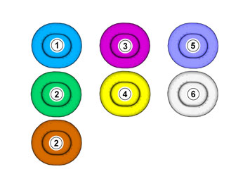
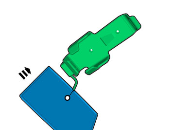
| | Note!
This colour chart displays (in colour print and electronic version) the importance of the different colours used in the images of the method steps. |
Used for focused component, the component with which you will do something. Used as extra colors when you need to show or differentiate additional parts. Used for attachments that are to be removed/installed. May be screws, clips, connectors, etc. Used when the component is not fully removed from the vehicle but only hung to the side. Used for standard tools and special tools. Used as background color for vehicle components.
|
| | |
|  | | IMG-349120 |
|
| | Activate and calibrate the Alcohol Analysing Start Inhibitor according to TJ (Technical Journal) 19265. |
|  | | IMG-332193 |
|
| | Set the ignition key to position 0. |
| | |
|  | | IMG-356946 |
|
| | |
|  | | IMG-356947 |
|
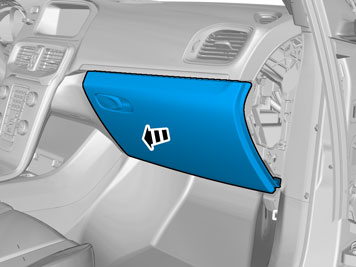
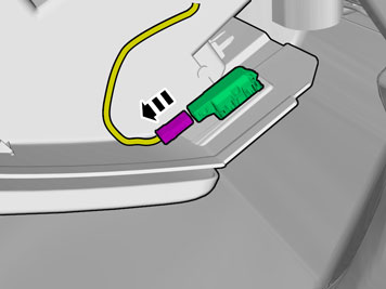
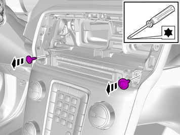
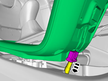
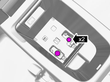
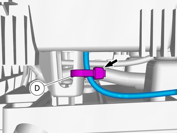
| | Disconnect the connector. |
|  | | IMG-356817 |
|
| | |
|  | | IMG-368301 |
|
| | |
|  | | IMG-356822 |
|
| | |
|  | | IMG-356862 |
|
| | |
|  | | IMG-356867 |
|
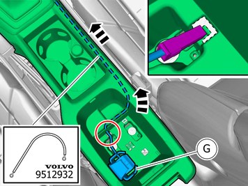
| | Disconnect the connector. |
|  | | IMG-356861 |
|
| | Disconnect the connector. |
| | Applies to installation in front of the centre console. |
|  | | IMG-368127 |
|
| | |
|  | | IMG-352821 |
|
| | |
|  | | IMG-352822 |
|
| | Disconnect the connector. |
|  | | IMG-361980 |
|
| | |
|  | | IMG-356816 |
|
| | |
|  | | IMG-352899 |
|
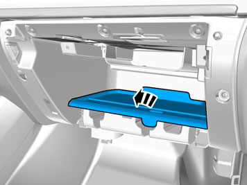
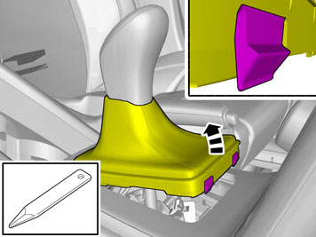
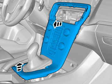
| | Remove the part carefully |
|  | | IMG-352929 |
|
| | |
|  | | IMG-352977 |
|
| | |
|  | | IMG-352901 |
|
| | |
|  | | IMG-352951 |
|
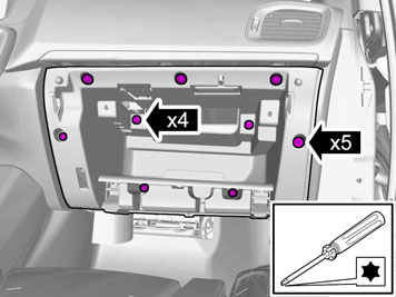
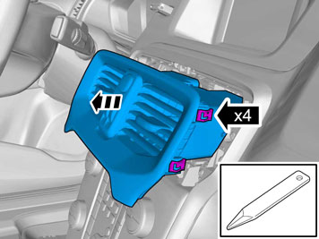
| | Disconnect the connector. Remove the panel. |
| | |
| | |
|  | | IMG-406020 |
|
| | |
|  | | IMG-356876 |
|
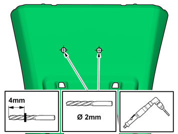
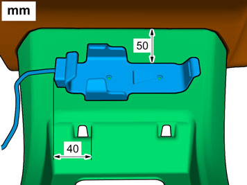
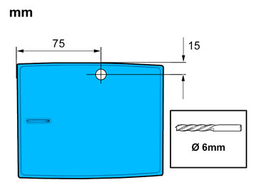
| | Measure and mark as illustrated. |
|  | | IMG-356882 |
|
| | |
|  | | IMG-356916 |
|
| | |
|  | | IMG-356920 |
|
| | Caution!
Make sure not to damage wiring, hoses or other components. |
Remove the swarf. |
|  | | IMG-356915 |
|
| | |
|  | | IMG-406021 |
|
| | |
|  | | IMG-356890 |
|
| | |
|  | | IMG-356871 |
|
| | Fold the carpet to the side. |
|  | | IMG-356897 |
|
| | Caution!
Make sure to locate the wiring in such a way that contact with any moving components is avoided. |
Pull the wiring through. Place any excess inside the floor carpet. |
| | Right-hand drive vehicles |
|  | | IMG-406022 |
|
| | |
|  | | IMG-356901 |
|
| | Measure and mark as illustrated. |
|  | | IMG-356904 |
|
| | |
|  | | IMG-356923 |
|
| | |
|  | | IMG-356921 |
|
| | Caution!
Make sure not to damage wiring, hoses or other components. |
Remove the swarf. |
|  | | IMG-356924 |
|
| | |
|  | | IMG-406023 |
|
| | |
|  | | IMG-356907 |
|
| | |
| | | IMG-356871 |
|
| | Fold the carpet to the side. |
|  | | IMG-356902 |
|
| | Caution!
Make sure to locate the wiring in such a way that contact with any moving components is avoided. |
|
|  | | IMG-357068 |
|
| | Pull the wiring through. Place any excess inside the floor carpet. |
| | Installation in Floor Console Compartment |
| | | IMG-368127 |
|
| | |
| | | IMG-352821 |
|
| | |
| | | IMG-352822 |
|
| | Disconnect the connector. |
| | | IMG-361980 |
|
| | |
| | | IMG-356816 |
|
| | |
| | | IMG-352899 |
|
| | Remove the part carefully |
| | | IMG-352929 |
|
| | |
| | | IMG-352977 |
|
| | |
| | | IMG-352901 |
|
| | |
| | | IMG-352951 |
|
| | Disconnect the connector. Remove the panel. |
|  | | IMG-361985 |
|
| | |
|  | | IMG-357001 |
|
| | |
|  | | IMG-357002 |
|
| | |
|  | | IMG-357011 |
|
| | |
|  | | IMG-357026 |
|
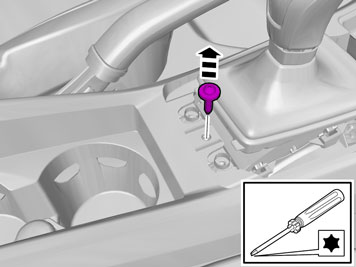
| | Facilitate cable routing by temporarily raising the floor bracket using a socket or similar. |
|  | | IMG-367726 |
|
| | Loosen the wiring harness or move it to the side. |
|  | | IMG-406024 |
|
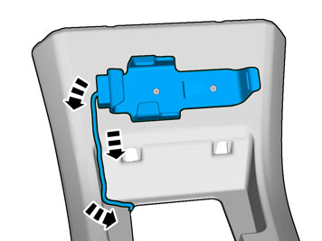
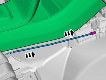
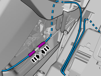
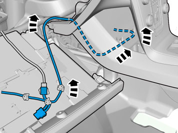
| | Caution!
Make sure to locate the wiring in such a way that contact with any moving components is avoided. |
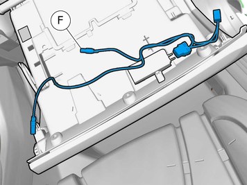
Route the cable harness to the existing cable harness. |
|  | | IMG-405853 |
|
| | |
|  | | IMG-357063 |
|
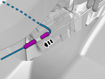
| | Place any excess inside the floor carpet. |
|  | | IMG-367727 |
|
| | |
|  | | IMG-357226 |
|
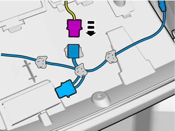
| | Caution!
Make sure that no part of the wiring harness is trapped. |
|
| | | IMG-357011 |
|
| | |
|  | | IMG-357109 |
|
| | |
|  | | IMG-357137 |
|
| | |
|  | | IMG-357139 |
|
| | |
|  | | IMG-357145 |
|
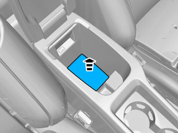
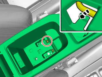
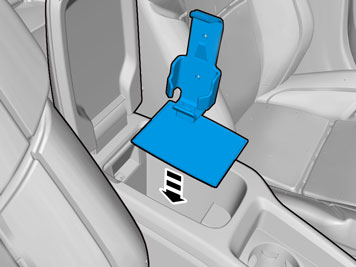
| | Note!
When placing the cradle in the floor bracket storage compartment, the cradle should always be positioned at the rear edge on left hand side. Applies to left and right hand drive cars. |
|
|  | | IMG-407421 |
|
| | |
|  | | IMG-407423 |
|
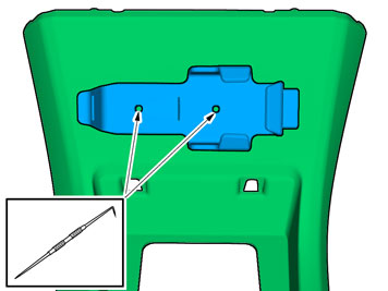
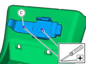
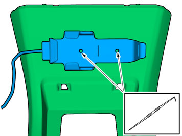
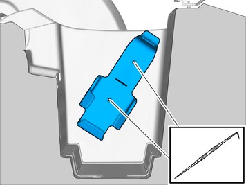
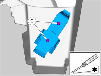
| | Use: Scribe
Make holes in the storage compartment using the point of a scriber. |
|  | | IMG-407425 |
|
| | |
| | |
|  | | IMG-406026 |
|
| | |
|  | | IMG-354769 |
|
| | |
|  | | IMG-356954 |
|
| | |
|  | | IMG-406027 |
|
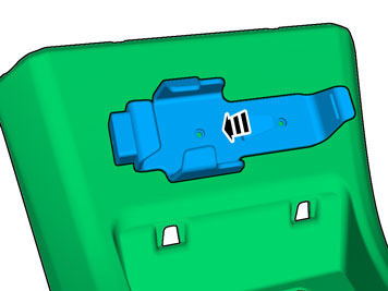
| | Install the part with butyl tape. |
|  | | IMG-356962 |
|
| | |
|  | | IMG-356987 |
|
| | |
|  | | IMG-405906 |
|
| | |
|  | | IMG-356992 |
|
| | |
|  | | IMG-349075 |
|
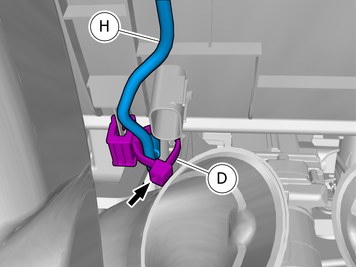
| | The lamp with the battery symbol should flash if the power supply is correct, if not, the black connector must be turned to switch poles. |
| | Right-hand drive vehicles |
| | | IMG-406026 |
|
| | |
| | | IMG-354769 |
|
| | |
|  | | IMG-357083 |
|
| | |
| | | IMG-406027 |
|
| | Install the part with butyl tape. |
|  | | IMG-356908 |
|
| | Fold the carpet to the side. |
| | | IMG-356871 |
|
| | Fold the carpet to the side. |
|  | | IMG-357097 |
|
| | Caution!
Make sure to locate the wiring in such a way that contact with any moving components is avoided. |
|
|  | | IMG-357098 |
|
| | Pull the wiring through. Place any excess inside the floor carpet. |
|  | | IMG-357102 |
|
| | |
| | | IMG-405906 |
|
| | |
|  | | IMG-357091 |
|
| | |
|  | | IMG-357180 |
|
| | The lamp with the battery symbol should flash if the power supply is correct, if not, the black connector must be turned to switch poles. |
| | |
| | Reinstall the removed parts in reverse order. |
|  | | IMG-242268 |
|
| | Download software (application) for the accessory's function according to the service information in VIDA. See VIDA or the accessories catalogue for software part number. |