2016 L.H.D

Installation Instruction

Installation instructions, accessories
Volvo Car Corporation Gothenburg, Sweden
S60 2016
S60 (11-18) 2016

Instruction NoVersionPart. No.Click to download PDF-version of this Installation Instruction
307566081.231316446, 30756607, 30756606
Steering wheel, leather


IMG-339612


Equipment
A0000162
IMG-239664

IMG-339613

IMG-335566


Cars equipped with SRS/SIPS (Airbag)


Warning!

Extra care must be taken when working on cars equipped with SRS/SIPS air bags. This is important to prevent:

1. Personal injury

2. Damage to or malfunction of the SRS/SIPS system.

Work on the SRS/SIPS systems or related components must always be carried out by an authorised Volvo workshop.


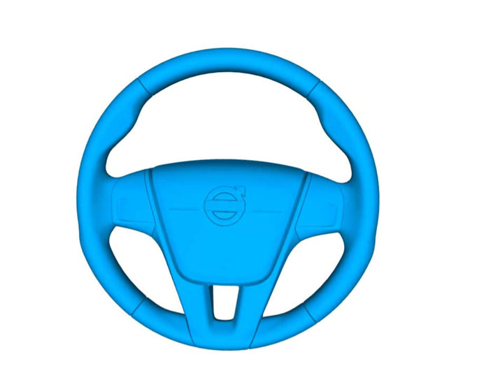
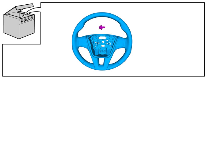
Is the car equipped with SRS (supplemental restraint system)?

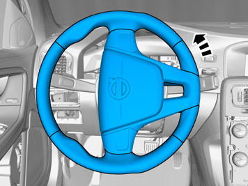
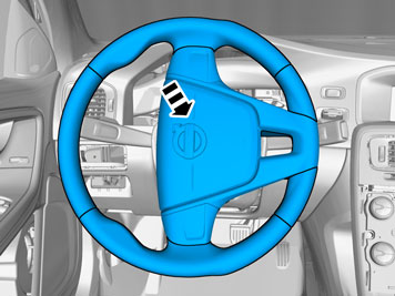
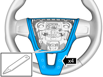
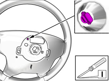
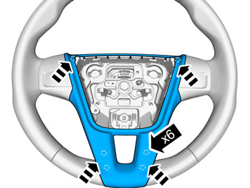
Cars equipped with a driver's airbag have the letters "SRS" imprinted on the centre panel of the steering wheel. Cars equipped with driver's and passenger airbags are marked with "SRS" on both the steering wheel centre panel and also on the dashboard close to the airbag.

If the car is equipped with SIPS (side impact protection system ) a "SIPS" decal is marked on both the front seats.

Cars equipped with inflatable curtains have the marking "SRS" on one of the panels along the posts on the inside of the car.

Cars equipped with SRS (supplemental restraint system) also have an "SRS" decal on the front windscreen.


Warning!

The air bag inflation areas must not be obstructed. Never place any objects, such as upholstery or accessories, within these areas. The panels must be able to open in the correct manner at the right time, otherwise there is an increased risk of personal injury in the event of a collision.


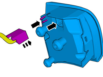
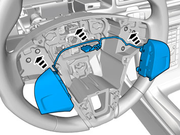
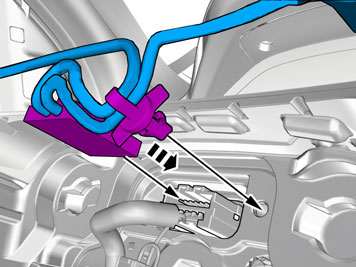
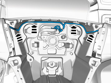
Do not damage the SRS wiring!

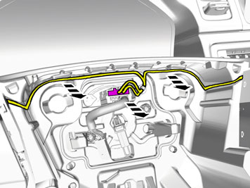
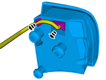
Do not trap, chafe, pierce or damage the SRS wiring. SRS wiring has orange casing and/or is plaited.

Steering and front suspension

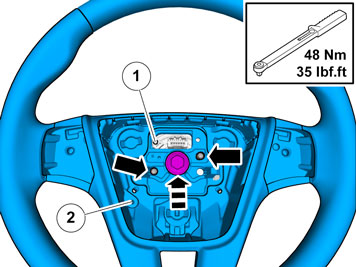
The contact reel in the SRS system can easily be damaged when working on the steering wheel, steering shaft or steering gear. Refer to the SRS (supplemental restraint system) Service Manual or service instructions in VIDA for information on carrying out such work. This is to prevent damage.

SRS warning lamp

If the SRS warning lamp lights after repairs have been carried out, take the car to an authorised Volvo workshop.

 
1
IMG-237320
 

  • Turn the ignition key to position I to release the steering wheel lock.

  • Disconnect the battery negative lead.


Note!

The SRS system remains active for a brief period after power is cut off. Thus, wait three minutes before starting work.


2
IMG-339640
 

  • Loosen the lever and pull the steering wheel console backwards.

  • Carefully prize off the rubber seal in the steering wheel cover all around.

3
IMG-329034
 

  • Carefully pull it off and remove the panel with the rubber seal.

4
IMG-328978
 

  • Carefully prize off the upper cover from the lower one at the rear. Remove the cover. It is fitted with clips at the sides.

5
IMG-339642
 

  • Turn the steering wheel a quarter turn so that the holes on the reverse of the steering wheel are accessible.

6A
IMG-328983
6B
IMG-328989
 

Illustrations A and B

  • Use a screwdriver that is at least 5.2 mm wide and with a length of 200-250 mm.

7A
IMG-328990
7B
IMG-329000
7C
IMG-329001
7D
IMG-339667
 

Illustration A, B, C and D

    Illustration A

  • Insert a screwdriver into the large hole on the rear of the steering wheel's rear face.

    Illustration B

  • Insert the tip of the screwdriver (1) under the lock spring (2).

    Illustration C

  • Turn the screwdriver so that the end presses the lock spring up until it can move past the locking catch (3)

    Illustration D

  • Carefully pull off one side of the steering wheel module. It is firmly attached.

  • Turn the steering wheel 180º.

  • Repeat for the lock spring on the other side.

  • Turn the steering wheel to neutral position.

8
IMG-329003
 

  • Carefully fold back the steering wheel module so that the connectors in the upper edge are accessible.

  • Press in the catches on the connectors (small illustration) and detach them.

  • Place the steering wheel module to one side.


Caution!

Position the steering wheel module with the front upwards in a secure position while carrying out the work.


9
IMG-329005
 

  • Grip the panel in the upper left-hand corner and carefully pull it loose until the pin releases. Use both hands.

  • Repeat the operation on the other side.

10
IMG-339674
 

  • Use a weatherstrip tool, turn and carefully pull the panel loose at the bottom on both sides. Put it to one side. There is a new component in the kit.

11
IMG-344509
 

  • Unplug the connector.

  • Disconnect the cables.

12
IMG-329008
 

  • Remove the left and right-hand keypad/keypad dummy from the steering wheel by gently prizing them off with a plastic weatherstrip tool.

  • Turn the weatherstrip tool to press out the keypad. They are firmly attached with three pins in the steering wheel, so force is required to remove them.

13
IMG-344121
 

  • Disconnect the connector from the keypad.

  • Repeat the operation on the other side.

14
IMG-329010
 

  • Loosen the screw in the steering wheel, but do not remove the screw.

  • Take the screw (1) and screw it in the bracket (2) in the contact reel.

  • Remove screw and steering wheel.

15
IMG-344511
 

  • Remove the clip for the cables.

16
IMG-339672
 

  • Take the new steering wheel and align the guide pins in the contact reel in the holes in the steering wheel.

  • Take a new screw for the steering wheel and screw it in by hand.

  • Remove the screw in the bracket (1) in the contact reel and reinsert it in position (2).

  • Tighten and torque tighten the steering wheel screw.

17
IMG-329012
 

  • Grip the panel in the upper left-hand corner and carefully pull it loose until the pin releases. Use both your hands.

  • Repeat the operation on the other side.

18
IMG-339673
 

  • Use a weatherstrip tool, turn and carefully pull the panel loose at the bottom on both sides.

19
IMG-344510
 

  • Connect the keypads on both sides.

20
IMG-344508
 

  • Press the keypads into place securely.

21
IMG-344507
 

  • Plug in the connector.

  • Install the clip.

22
IMG-344506
 

  • Install the cables.

23
IMG-339675
 

  • Take the panel and firmly press into the steering wheel.

24
IMG-329019
 

  • Take the steering wheel module and check that the three spring-loaded holders are firmly attached to it. If any holder has become trapped in the bottom of the steering wheel, remove it and fit it on the steering wheel module.

25
IMG-329020
 

  • Plug in the two connectors for the steering wheel module.

  • Position the steering wheel module in the centre of the steering wheel and press it firmly into bottom of the steering wheel.

  • Check that it is fitted firmly and can be pressed in all around.

26
IMG-329021
 

27
IMG-329022
 

28
IMG-339676
 

29
IMG-337646
 

  • Set the ignition key to position 0.

  • Reconnect the battery negative lead

30
IMG-336904


Warning!

When the ignition is to be switched on for the first time after the battery has been disconnected, this must be done whilst by standing outside the vehicle, stretching your arm in and avoiding the working area for the airbags.


  • Set the ignition key to position II.