| | |
|  | | IMG-217765 |
|
| | |
|  | | IMG-217766 |
|
| | |
|  | | IMG-217767 |
|
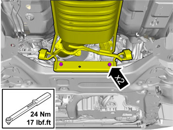
| | Undo the front screw in the mounting for the centre console. Take the bracket for the passenger compartment connector from the kit and tighten it in with the previously removed screw. Align the bracket so that it is straight and torque tighten the screw to 24 Nm (18 lbf.ft.).
|
|  | | IMG-217768 |
|
| | |
|  | | IMG-217769 |
|
| | |
|  | | IMG-217770 |
|
| | Press a locking sleeve (from the kit) onto the passenger compartment connector socket. Slide the locking sleeve as far along the terminal for the passenger compartment connector socket as possible. Take a carpet knife and cut a slit in the carpet just in front of the locking sleeve. Make the cut as long as the diameter of the locking sleeve.
Note!
Do not damage any wiring and hoses under the carpet. |
|
|  | | IMG-217771 |
|
| | |
|  | | IMG-217772 |
|
| | |
|  | | IMG-217773 |
|
| | |
|  | | IMG-231820 |
|
| | |
|  | | IMG-231309 |
|
| | |
|  | | IMG-318204 |
|
| | Applies to cars with 5-cyl. diesel and twin turbos |
|  | | IMG-318206 |
|
| | |
|  | | IMG-318207 |
|
| | |
|  | | IMG-318208 |
|
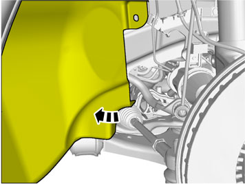
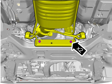
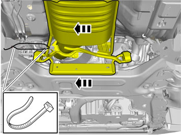
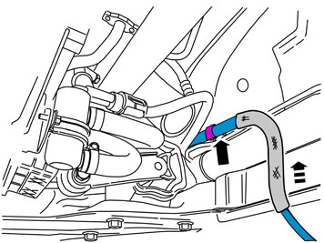
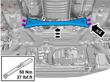
| | Carefully move the catalytic converter to the left side towards the stop. Secure the catalytic converter with cable ties in the hole for the screw to the removed strut and the stay on the catalytic converter.
|
|  | | IMG-231821 |
|
| | |
|  | | IMG-231822 |
|
| | Applies to cars with already installed engine heater |
|  | | IMG-231823 |
|
| | |
|  | | IMG-231826 |
|
| | |
|  | | D3601932 |
|
| | Grease in the O-ring on the connector to the front socket, both connectors on the junction connector and the O-ring on the passenger compartment connector's joint cable, using low temperature grease P/N 1161427.
Note!
Do not get any grease on the surfaces of the connector. |
|
|  | | IMG-231829 |
|
| | Press the cables firmly into the junction connector in accordance with the following: Cable (1) to the front socket. Cable (2) to the passenger compartment connector socket. Cable (3) to the heater. Take three locking sleeves from the kit and install them over the joints.
|
|  | | IMG-231830 |
|
|  | | IMG-318243 |
|
| | Illustration A Applies to cars with 5-cylinder engines Illustration B Applies to cars with 5-cyl. diesel and twin turbos Use the entire length of the cable from the front socket and route the junction connector as far to the right as possible. If necessary, move the clips on the sub frame's upper edge to the right. Insert the junction connector in the space in the sub-frame and tighten down the junction connector around the rear cable with a cable tie in the hole at the top of the sub-frame.
|
|  | | IMG-231831 |
|
|  | | IMG-231832 |
|
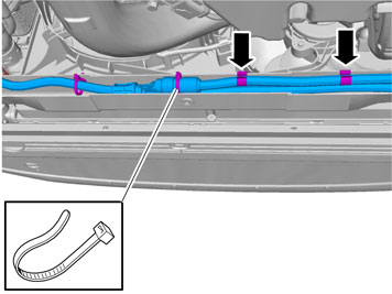
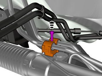
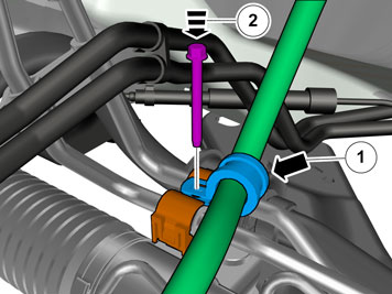
| | Applies to all models Illustrations A and B Route the cable for the passenger compartment connector the same way as the cable for the heater up to the steering gear. Take three tie straps from the kit and clamp the cable into the heater cable. Position the cable (1) for the passenger compartment connector inside the bracket (2) in the front edge of the subframe's front right-hand corner (Illustration B).
|
|  | | IMG-231833 |
|
| | |
|  | | IMG-231834 |
|
| | Note!
Make sure that the cable is routed so that it does not make contact with the pulley or the belt for the air conditioning compressor. |
|
|  | | IMG-231837 |
|
| | |
|  | | IMG-359905 |
|
|  | | IMG-359906 |
|
| | Note!
Do not clamp the cable so that it is in direct contact with brake pipes, fuel lines, AC pipes or pipes to the power steering. |
|
|  | | IMG-231839 |
|
| | |
|  | | IMG-359911 |
|
| | Take the radiation shield from the kit and thread it onto the cable to the front engine block heater socket. Route the radiation shield to the cable clamp. Adjust the length of the radiation protection up to the hole for the rubber grommet and cut off the excess.
|
|  | | IMG-217774 |
|
| | Note!
Do not get any grease on the surfaces of the connector. |
Thread the rubber grommet onto the cable. Adjust the length of the cable from the rubber grommet and out into the engine compartment so that it runs true and does not come into contact with any moving parts in the engine compartment. Conceal all cable excess under the mat in the passenger compartment.
|
|  | | IMG-217775 |
|
| | Insert the cable into the passenger compartment. Press the rubber grommet into the cowl panel. Take the grey tie strap from the kit and tighten the radiation shield upper end into the cable.
|
|  | | IMG-231335 |
|
| | |
|  | | IMG-318264 |
|
| | Applies to cars with 5-cyl. diesel and twin turbos |
|  | | IMG-318266 |
|
| | |
|  | | IMG-318267 |
|
| | |
|  | | IMG-318268 |
|
| | |
|  | | IMG-217778 |
|
| | |
|  | | IMG-231842 |
|
| | |
|  | | IMG-231843 |
|
| | |
|  | | IMG-289523 |
|
| | |
|  | | IMG-289464 |
|
| | |
|  | | IMG-231844 |
|
| | |
|  | | IMG-217776 |
|
|  | | IMG-217777 |
|
| | Illustrations A and B Note!
Ensure that no grease gets onto the connector surfaces. |
Connect the cable to the passenger compartment connector socket. Press a locking sleeve (from the kit) over the joint. Fold the carpet back into position and install the passenger compartment connector socket using both the screws.
|
|  | | IMG-234260 |
|
| | |