| | |
|  | | R8504142 |
|
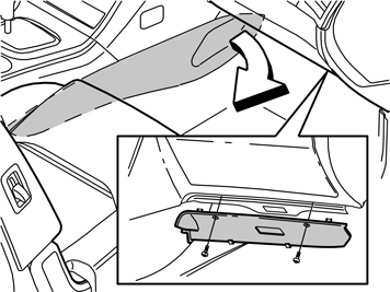
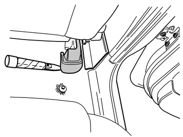
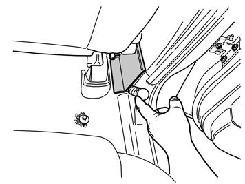
| | Turn the ignition key to position 0. Remove the right-hand side panel of the centre console by pulling it away starting at the front edge and then backwards until all clips have released. Remove the sound barrier on the right-hand side by first removing the two screws and then prizing it away at the top edge.
|
|  | | R8504241 |
|
| | |
|  | | R8504169 |
|
| | |
|  | | R8504170 |
|
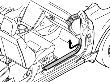
| | Detach the right-hand front door's sill trim panel. Pull it away starting at the front edge until the clip there has released. Continue backwards until the remaining clips have released. Unhook it from the B-pillar panel and place it to one side.
|
|  | | R8504295 |
|
| | |
|  | | R3603720 |
|
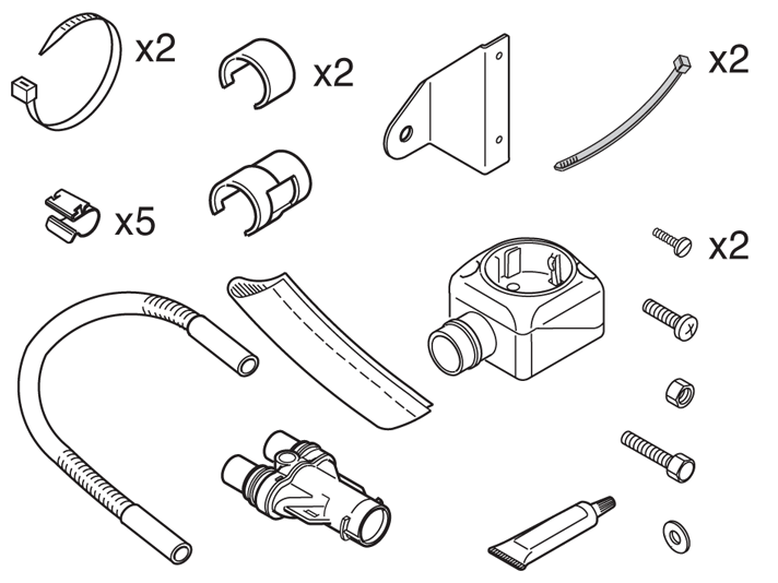
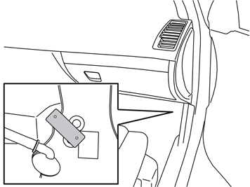
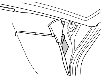
| | Remove the lower piece of tape, which is fitted where the bracket shall be screwed in. Take the bracket and screw from the kit. Install the bracket in the existing weld nut, from where the piece of tape was removed. Turn the bracket so that it is fitted as illustrated. Install the connector loosely and check that it is fitted on straight, with the internal power connector forwards. Tighten the bracket to 10 Nm (7 lbf.ft.). If the car is equipped with a child seat mounting then the bracket for the passenger compartment connector socket must be fitted over this and secured with an M6 screw. Tightening torque 10 Nm (7 lbf.ft.).
|
|  | | R8703679 |
|
| | |
|  | | M3603137 |
|
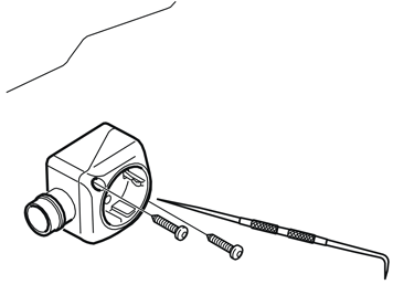
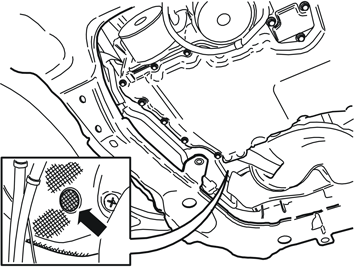
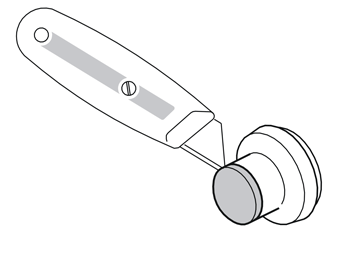
| | Take a screw and the passenger compartment connector socket from the kit. Tighten the passenger compartment connector socket to the bracket in the upper mounting. Insert the double ended scriber into the lower mounting for the passenger compartment connector socket. Make a hole in the carpet opposite the lower hole on the bracket. Tighten the lower mounting for the passenger compartment connector socket using a screw from the kit.
|
|  | | M3603138 |
|
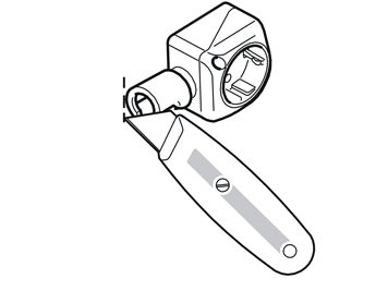
| | Press a locking sleeve (from the kit) onto the passenger compartment connector socket. Slide the locking sleeve as far along the terminal for the passenger compartment connector socket as possible. Take a carpet knife and cut a slit in the carpet just in front of the locking sleeve. Make the cut as long as the diameter of the locking sleeve.
Note!
Do not damage any wiring and hoses under the carpet. |
Remove the passenger compartment connector socket from the bracket.
|
|  | | R3501343 |
|
| | |
|  | | R3501493 |
|
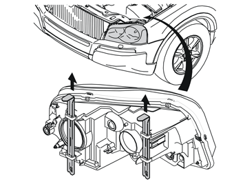
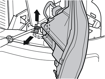
| | Carefully prize up the catch on the connector for the headlamp using a screwdriver. Pull the catch up completely, detach the connector and place the headlamp to one side.
|
|  | | R2900490 |
|
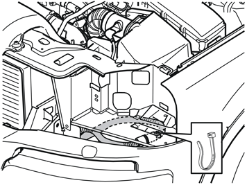
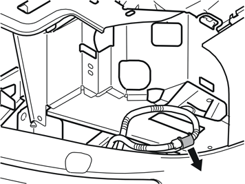
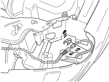
| | Applicable for steps 12-17 is that the location of the above mentioned cable joints and junction connector is under the plate under the left-hand headlamp. Applies to cars with 8-cylinder engine where engine block heater is installed Remove the tie strap securing the cable to the front socket. Pull the cable forward.
|
|  | | R3602976 |
|
| | Applies to cars with 8-cylinder engine where engine block heater is installed Remove the locking sleeve over the joint on the cables for the engine block heater. Pull the cables away from each other.
|
|  | | IMG-233745 |
|
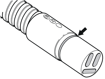
| | Applies to cars with 6-cylinder engine where engine block heater is installed Remove the tie strap securing the cable to the front engine block heater socket. Pull the cable forward. Remove the locking sleeve over the joint on the cables for the engine block heater and pull the cables away from each other.
|
|  | | D3601932 |
|
| | |
|  | | R3602939 |
|
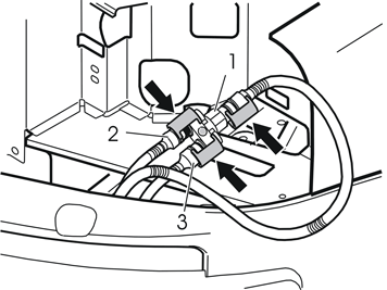
| | Applies to all models Connect the cable for the front socket to socket (1) on the branch connector. Firmly press the connector in and press in a locking sleeve from the kit over the joint. Connect the long cable for the passenger compartment connector socket from the kit to any connector (2 or 3) on the branch connector. Firmly press the connector in and press in a locking sleeve from the kit over the joint. Connect the cable for the engine block heater to the remaining connector on the branch connector. Firmly press the connector in and press in a locking sleeve from the kit over the joint.
|
|  | | R2900491 |
|
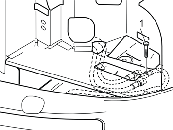
| | Applies to cars with 8-cylinder engine Route the new cable for the passenger compartment connector socket on to the brake fluid reservoir the same way as the existing cable for the engine block heater.
Applies to cars with 6-cylinder engine Route the cable as shown in Illustration 18.
Applies to all models Take a screw, nut and washer from the kit. Secure the branch connector in the hole in the plate (1). Take a new tie strap from the kit and replace the tie strap removed in steps 12 and 14 respectively.
|
|  | | R3603718 |
|
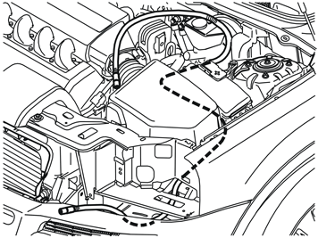
| | Applies to all models Route the cable for the passenger compartment connector socket under the left-hand headlamp. Route it backwards along the left-hand side of the air filter and between air filter and fuse holder. Continue to route it backwards, under the ABS system and up between the cable duct and brake fluid reservoir.
Note!
Check that the cable does not chafe against sharp edges or moving parts in the engine compartment. |
|
|  | | R2900495 |
|
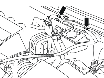
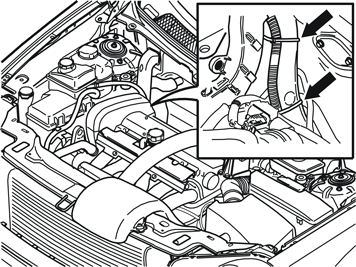
| | Applies to cars with 8-cylinder engine Detach the cable from the engine block heater from the two clips above the brake fluid reservoir.
|
|  | | R3603715 |
|
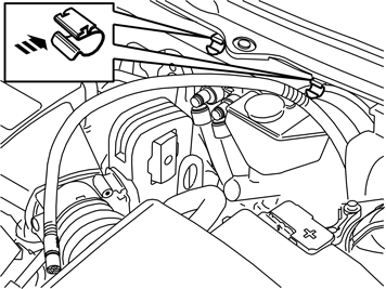
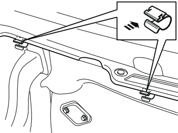
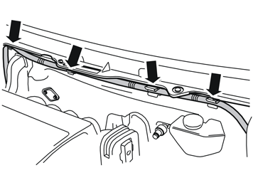
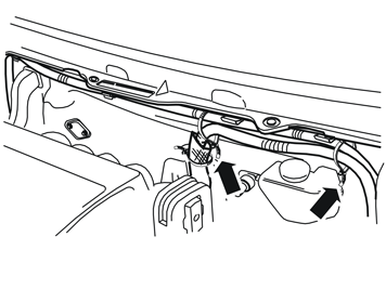
| | Applies to cars with 6-cylinder engine Take two clips from the kit and install them on the edge of the plate at the front edge of the panel above the windscreen wiper arms.
|
|  | | R2900496 |
|
| | |
|  | | R2900498 |
|
| | |
|  | | M2900499 |
|
| | Applies to cars with 8-cylinder engine Take two tie straps from the kit and clamp the cable for the heater which was detached earlier, to the newly routed cable for the passenger compartment connector socket.
|
|  | | R2900501 |
|
| | |
|  | | R7700583 |
|
| | |
|  | | R6100412 |
|
| | |
|  | | R2102945 |
|
| | |
|  | | R2900497 |
|
| | |
|  | | R2900500 |
|
| | |
|  | | R3603721 |
|
| | |
|  | | R2900516 |
|
| | |
|  | | R2900517 |
|
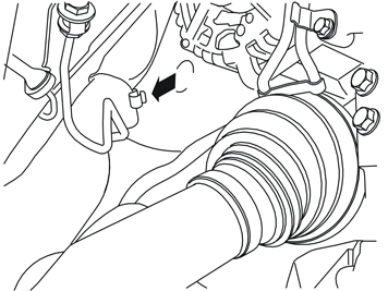
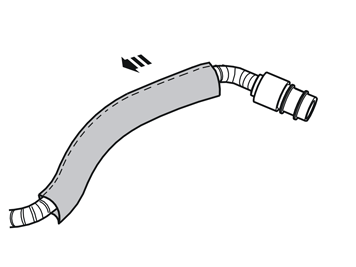
| | Grease in the rubber grommet using low temperature grease P/N 1161427 in order to make it easier to insert the cable and rubber grommet into the hole in the cowl panel. Guide the cable into the rubber grommet.
|
|  | | R3603735 |
|
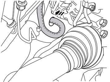
| | Guide the cable into the hole in the cowl wall and press the rubber grommet into place in the hole, either by pulling it into place from inside the passenger compartment, or carefully pressing it into place with a long large screwdriver/wide end of a short pry bar.
Note!
These must not be sharp or they can damage the cables/rubber grommet. |
Adapt the length of the cable from the rubber grommet, at the installed clip and out in the engine compartment.
|
|  | | R3603734 |
|
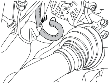
| | Caution!
Check that the cable is routed so that it does not come into contact with the alternator belt, or chafe against sharp edges in the engine compartment. |
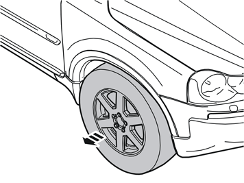
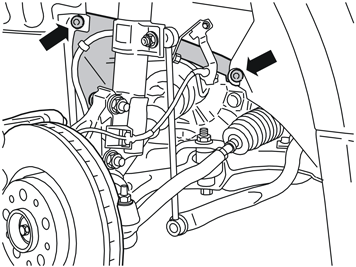
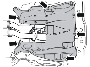
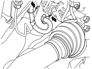
Reinstall the small protective panel in the wheel housing. Remount the wheel and tighten the bolts to 140 Nm (103 lbf.ft.). Reinstall the engine splash guard and torque tighten the screws to 25 Nm (18.5 lbf.ft.). Connect and reinstall the left-hand headlamp.
|
|  | | R3603736 |
|
| | |
|  | | M3603139 |
|
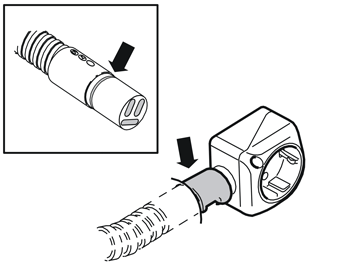
| | Route the cable from the engine compartment through the hole in the carpet. Grease in the O-ring with low temperature grease P/N 1161427.
Note!
! Make sure that no grease gets onto the connector surfaces. |
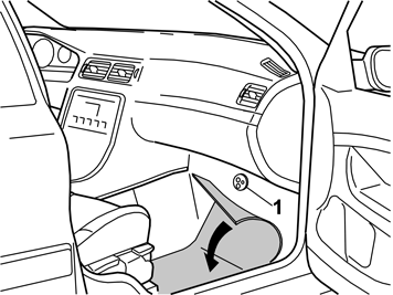
Connect the cable to the passenger compartment connector socket. Press a locking sleeve (from the kit) over the joint. Fold the carpet back into position and install the passenger compartment connector socket using both the screws.
Reinstall: the sound barrier the sill trim panel the cover panel in the lower edge of the B-pillar panel the cover panel for the seat's mounting the centre console's right-hand side panel.
|


