| | |
|  | | IMG-352121 |
|
| | |
|  | | IMG-352126 |
|
| | |
|  | | IMG-352127 |
|
| | |
|  | | IMG-352131 |
|
| | |
|  | | IMG-340010 |
|
| | |
|  | | IMG-332193 |
|
| | Note!
Wait at least one minute before unplugging the connectors or removing other electrical equipment. |
|
|  | | IMG-292804 |
|
| | |
|  | | IMG-292826 |
|
| | |
|  | | IMG-345113 |
|
| | |
|  | | IMG-339997 |
|
| | |
|  | | IMG-339998 |
|
| | |
|  | | IMG-339999 |
|
| | |
|  | | IMG-282533 |
|
| | |
|  | | IMG-340192 |
|
| | |
|  | | IMG-296139 |
|
| | |
|  | | IMG-296140 |
|
| | Applies to vehicles with an automatic gearbox |
|  | | IMG-282545 |
|
| | |
|  | | IMG-340001 |
|
|  | | IMG-340196 |
|
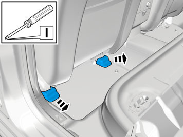
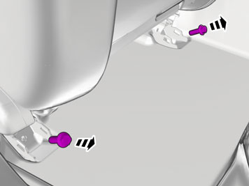
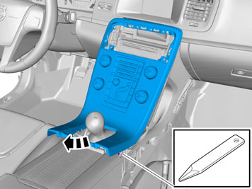
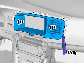
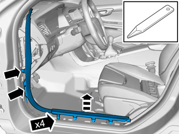
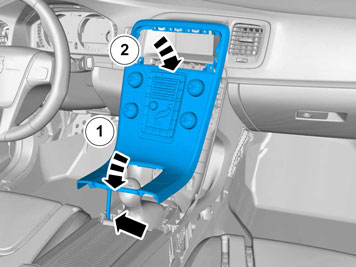
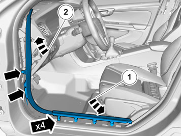
| | Illustrations A and B Carefully pry off the centre console panel starting on both sides at the rear edge. It is secured by two clips along the long sides. On manual gearboxes, the gear lever boot is secured by four catches (1) around the gear lever panel, (Image B). Lift it up slightly and make sure that all cables are free from the gear lever carrier and components in the tunnel console, and lift it out.
|
|  | | IMG-345114 |
|
|  | | IMG-360002 |
|
|  | | IMG-360001 |
|
|  | | IMG-345115 |
|
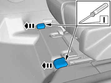
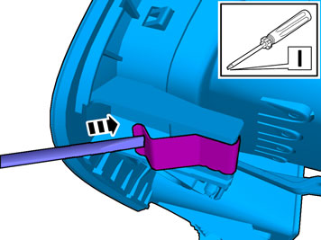
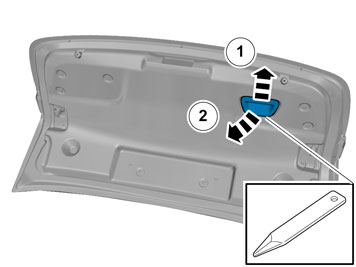
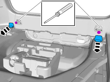
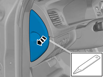
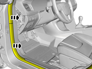
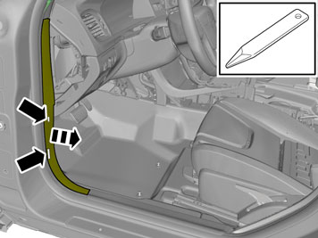
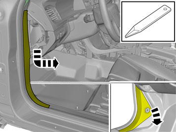
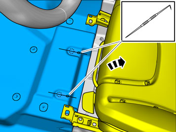
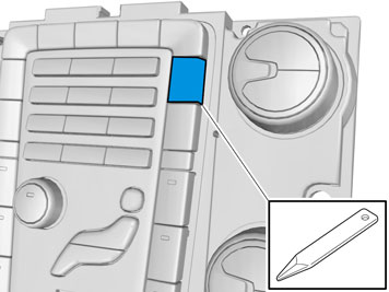
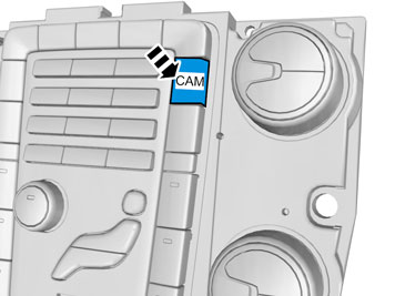
| | Illustration A, B, C and D Use: Electrician's screwdriver |
|  | | IMG-345232 |
|
| | |
|  | | IMG-345233 |
|
| | |
|  | | IMG-340008 |
|
| | |
|  | | IMG-348526 |
|
| | Applies to vehicles with 5" display Note!
If the connection on the display is missing, the display must be changed. |
|
|  | | IMG-352166 |
|
| | Applies to vehicles with 7" display |
|  | | IMG-345776 |
|
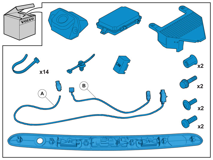
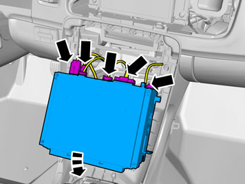
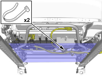
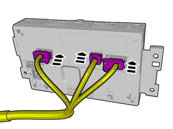
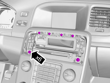
| | Applies to all models Note!
The number of connectors, cables and cable ties can vary depending on the vehicle's equipment level. |
|
|  | | IMG-341683 |
|
| | |
|  | | IMG-340012 |
|
| | |
|  | | IMG-340016 |
|
| | |
|  | | IMG-340017 |
|
| | |
|  | | IMG-340018 |
|
| | |
|  | | IMG-339904 |
|
| | |
|  | | IMG-340019 |
|
| | |
|  | | IMG-340020 |
|
| | |
|  | | IMG-340021 |
|
| | |
|  | | IMG-352093 |
|
| | Carry out on both sides. Use: Screwdriver.
|
|  | | IMG-339894 |
|
| | |
|  | | IMG-340022 |
|
| | |
|  | | IMG-303083 |
|
| | |
|  | | IMG-340026 |
|
| | |
|  | | IMG-340028 |
|
| | |
|  | | IMG-339896 |
|
| | |
|  | | IMG-340029 |
|
| | |
|  | | IMG-339918 |
|
| | |
|  | | IMG-340032 |
|
| | |
|  | | IMG-340033 |
|
| | |
|  | | IMG-340034 |
|
| | |
|  | | IMG-340035 |
|
| | Note!
Fold to one side from the bonnet opener. |
|
|  | | IMG-340036 |
|
| | |
|  | | IMG-340037 |
|
| | |
|  | | IMG-339901 |
|
| | |
|  | | IMG-339903 |
|
| | |
|  | | IMG-340038 |
|
| | |
|  | | IMG-340039 |
|
| | |
|  | | IMG-340040 |
|
| | |
|  | | IMG-340041 |
|
| | Connect the connector to the camera. Press the contact in the other end of the cable in the supplied isolator so that it locks. Press the grey lock into the isolator.
|
|  | | IMG-340057 |
|
| | |
|  | | IMG-339906 |
|
|  | | IMG-340253 |
|
| | |
|  | | IMG-339900 |
|
| | |
|  | | IMG-341685 |
|
| | |
|  | | IMG-339909 |
|
| | |
|  | | IMG-339907 |
|
| | |
|  | | IMG-340254 |
|
| | |
|  | | IMG-339908 |
|
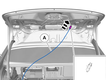
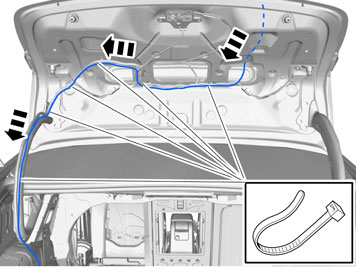
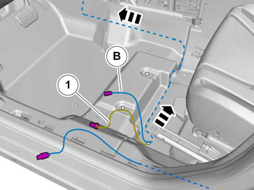
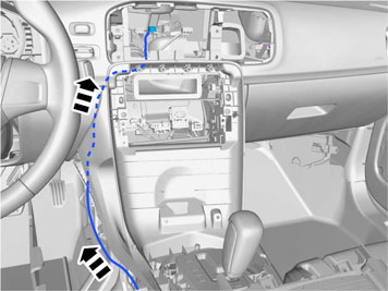
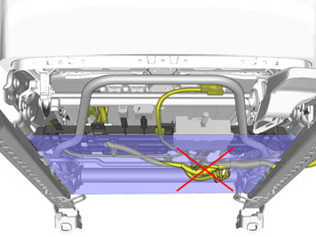
| | Route the existing cable (1) to the control module's power supply (under the carpet) and place it in the hole in the carpet. Take the remaining cable harness (B), place it in the hole in the carpet. Route under the carpet up towards the hole for the display.
|
|  | | IMG-340115 |
|
| | |
|  | | IMG-340256 |
|
| | |
|  | | IMG-340257 |
|
| | |
|  | | IMG-329273 |
|
| | |
|  | | IMG-340259 |
|
| | |
|  | | IMG-329275 |
|
| | |
|  | | IMG-329276 |
|
| | |
|  | | IMG-367232 |
|
| | Check that the cable harness does not hang and touch the newly installed control module. |
|  | | IMG-367234 |
|
| | Push up and secure the cable harness as necessary. |
|  | | IMG-342116 |
|
| | |
|  | | IMG-342121 |
|
| | |
|  | | IMG-268064 |
|
| | |
|  | | IMG-348748 |
|
| | Illustrations A and B Note!
The number of connectors, cables and cable ties can vary depending on the vehicle's equipment level. |
|
|  | | IMG-351626 |
|
| | |
|  | | IMG-340130 |
|
| | |
|  | | IMG-340131 |
|
| | |
|  | | IMG-340147 |
|
|  | | IMG-340148 |
|
| | |
|  | | IMG-340564 |
|
| | |
|  | | IMG-340580 |
|
|  | | IMG-340554 |
|
| | |
|  | | IMG-340700 |
|
| | |
|  | | IMG-340711 |
|
| | |
|  | | IMG-340555 |
|
| | | IMG-340580 |
|
| | |
|  | | IMG-340563 |
|
| | |
|  | | IMG-340149 |
|
| | |
|  | | IMG-340150 |
|
| | |
|  | | IMG-340151 |
|
| | |
|  | | IMG-339905 |
|
| | |
|  | | IMG-340288 |
|
| | |
|  | | IMG-340152 |
|
| | |
|  | | IMG-340153 |
|
| | |
|  | | IMG-339916 |
|
| | |
|  | | IMG-339899 |
|
| | |
|  | | IMG-242268 |
|
| | |
|  | | IMG-275777 |
|
| | Calibrate the camera. Information can be found in VIDA under: DIAGNOSTICS VEHICLE COMMUNICATION Advanced PAC Service calibration, parking camera
|