| | |
|  | | IMG-245980 |
|
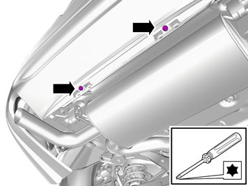
| | Note!
Wait at least one minute before unplugging the connectors or removing other electrical equipment. |
|
|  | | IMG-340642 |
|
| | |
|  | | IMG-347701 |
|
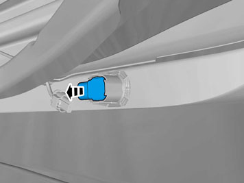
| | Applies to vehicles with parking assistance |
|  | | IMG-347702 |
|
| | |
|  | | IMG-347626 |
|
| | |
|  | | IMG-344142 |
|
| | |
|  | | IMG-344141 |
|
| | |
| | | IMG-344142 |
|
| | |
|  | | IMG-344251 |
|
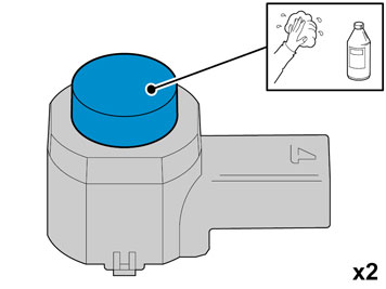
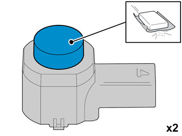
| | Caution!
Protect the connections' contact surfaces against paint. |
Paint the sensors in colour code 426. Use Volvo Touch-up paint. (Only use base coat.) Use Volvo Varnish. P/N: 9437467
|
|  | | IMG-333934 |
|
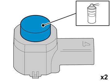
| | Caution!
The paint must have dried after the first application. |
|
|  | | IMG-353515 |
|
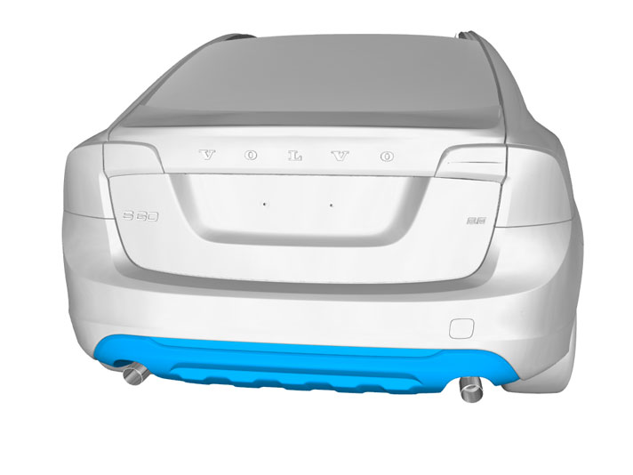
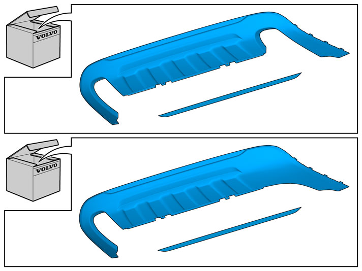
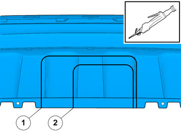
| | Applies to all models Take the Skid plate from the kit. Apply tape to the outside of the bumper cover, opposite the markings on the inside. Do this to protect the paint from the saw when cutting out the cut-out for the tow hitch.
|
|  | | IMG-353440 |
|
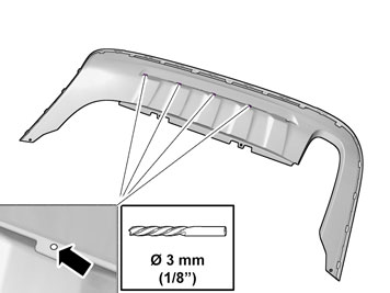
| | Marking for Detachable towbar Marking for Fixed towbar
|
|  | | IMG-340098 |
|
| | Applies to vehicles with parking assistance |
|  | | IMG-340100 |
|
| | |
|  | | IMG-340103 |
|
| | |
|  | | IMG-340114 |
|
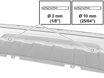
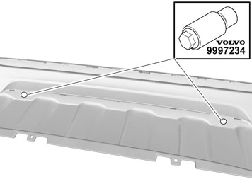
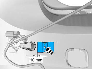
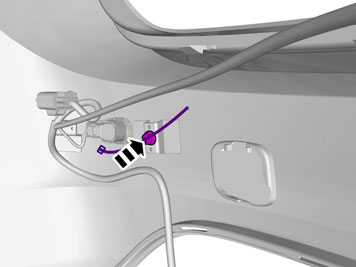
| | Enlarge the holes in the bumper casing using a hole cutter. Use special tool: 9997234. Place the hole tool's support sleeve on the inside, and the cutting part on the outside of the bumper casing.
|
|  | | IMG-340116 |
|
| | |
|  | | IMG-353514 |
|
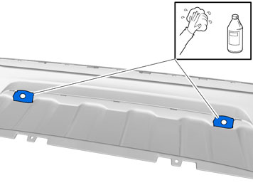
| | Apply primer to the hole edges that were created when making holes. Apply a thin and even layer of primer to the cleaned plastic surface.
Note!
Not to the inside of the casing. |
Use: Bonding primer for plastic. P/N: 31335448
Hint
Spray primer into the cap of the can and apply with a brush. |
Caution!
Allow to dry at a temperature of at least +20°C for 10 min, before painting. |
Note!
Also read the instructions on the spray can. |
|
|  | | IMG-340137 |
|
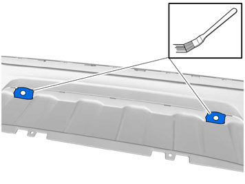
| | Apply a thin and even layer of activator to an area around the holes that is slightly larger than a sensor holder.
Note!
Not to the hole edges. |
Allow to dry for at least 10 minutes. Use: 8637076 - Activator.
|
|  | | IMG-353519 |
|
| | |
|  | | IMG-353518 |
|
| | |
| | | IMG-353514 |
|
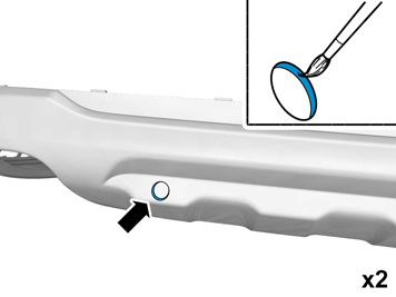
| | Apply paint to the hole edges that were created when making holes. Use Volvo Touch-up paint. (Only use base coat.) Use Volvo Varnish. P/N: 9437467
Hint
Spray paint into the cap of the can and apply with a brush. |
|
|  | | IMG-343213 |
|
| | |
|  | | IMG-337277 |
|
| | |
|  | | IMG-337278 |
|
| | |
|  | | IMG-337279 |
|
|  | | IMG-337311 |
|
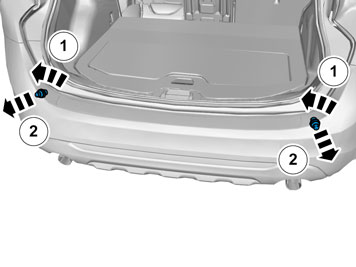
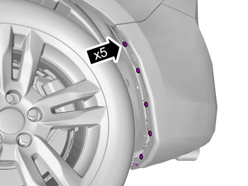
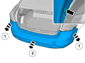
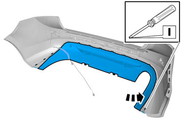
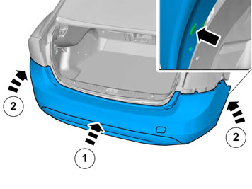
| | Illustrations A and B Note!
Get help from a colleague for this procedure. |
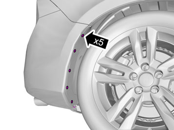
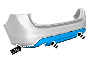
Unhook the end of the bumper cover at the front edge from the catches on both sides. Carefully pull off the ends of the bumper cover until the catches at the rear edge, at the rear fender and under the tail lamp, release. Pull the bumper cover backwards.
Applies to vehicles with parking assistance |
|  | | IMG-347703 |
|
| | Applies to vehicles with parking assistance |
|  | | IMG-340226 |
|
| | |
|  | | IMG-340227 |
|
| | Applies to vehicles with parking assistance |
|  | | IMG-340228 |
|
| | |
| | | IMG-353515 |
|
| | |
|  | | IMG-340204 |
|
|  | | IMG-340200 |
|
| | |
|  | | IMG-340202 |
|
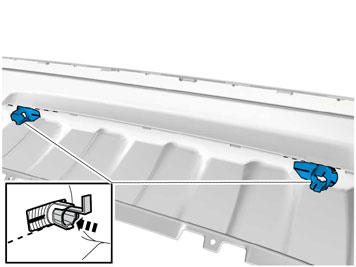
| | Note!
Check that sufficient number of holders have been cut off before the protective tape is removed, by placing the holders with tools in the drilled holes. |
|
|  | | IMG-340203 |
|
| | |
|  | | IMG-340198 |
|
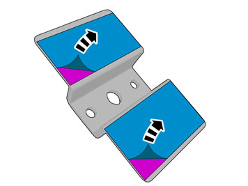
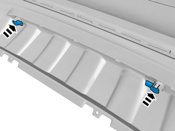
| | Note!
The holders must be mounted turned against the holes as illustrated. The holders must also be horizontal and in line with the edge of the skid plate. |
|
|  | | IMG-340786 |
|
| | |
|  | | IMG-340188 |
|
| | |
|  | | IMG-340189 |
|
| | |
|  | | IMG-340191 |
|
| | |
|  | | IMG-340179 |
|
| | Applies to vehicles with parking assistance |
|  | | IMG-340181 |
|
| | |
|  | | IMG-344616 |
|
| | |
|  | | IMG-340186 |
|
| | |
|  | | IMG-353521 |
|
| | |
|  | | IMG-337324 |
|
|  | | IMG-338572 |
|
| | Applies to all models Illustrations A and B |
|  | | IMG-347831 |
|
| | |
| | | IMG-337278 |
|
| | |
| | | IMG-337277 |
|
| | |
| | | IMG-340642 |
|
| | |
|  | | IMG-340143 |
|
| | |
|  | | IMG-340171 |
|
| | |
|  | | IMG-340142 |
|
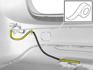
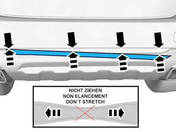
| | Note!
Do not stretch the tape when attaching. |
|