| | |
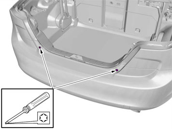
|  | | IMG-221940 |
|
| | |
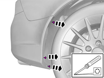
|  | | IMG-334528 |
|
| | |
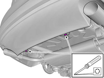
|  | | IMG-242961 |
|
| | |
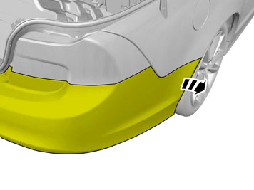
|  | | IMG-242962 |
|
| | |
|  | | IMG-242963 |
|
| | |
|  | | IMG-334529 |
|
| | |
|  | | IMG-242964 |
|
| | |
|  | | IMG-226483 |
|
| | |
|  | | IMG-334530 |
|
| | |
|  | | IMG-334531 |
|
| | |
|  | | IMG-334532 |
|
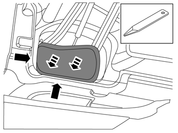
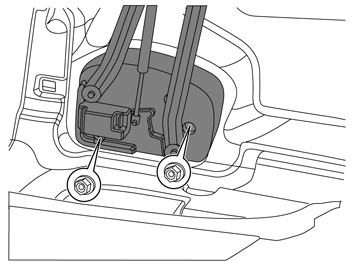
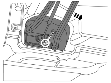
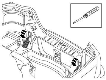
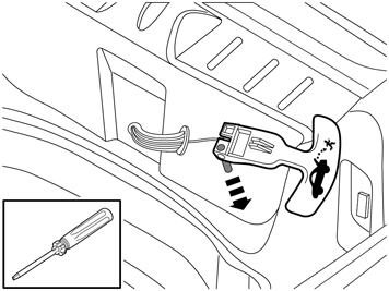
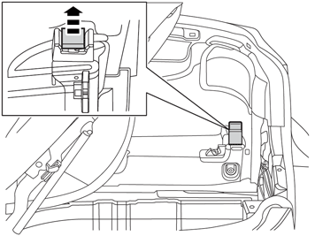
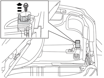
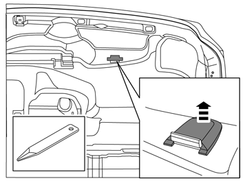
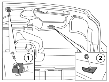
| | Remove: the clip the screw the tool box.
|
|  | | IMG-334533 |
|
| | |
|  | | IMG-334534 |
|
| | |
|  | | IMG-242966 |
|
| | |
|  | | IMG-334535 |
|
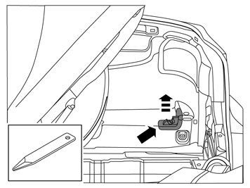
| | Applies to vehicles with emergency opening handle in the luggage compartment |
|  | | IMG-334536 |
|
| | |
|  | | IMG-334537 |
|
| | |
|  | | IMG-334538 |
|
| | |
|  | | IMG-334539 |
|
| | |
|  | | IMG-334540 |
|
| | |
|  | | IMG-242968 |
|
| | |
|  | | IMG-221974 |
|
| | |
|  | | IMG-242969 |
|
| | |
|  | | IMG-242970 |
|
| | Mark out the stop braces for the roof in relation to the screws and nuts on the right side. Remove the screw, nut and the roof's stop braces.
|
|  | | IMG-221976 |
|
| | |
|  | | IMG-359901 |
|
| | |
|  | | IMG-334508 |
|
| | |
|  | | IMG-334509 |
|
| | |
|  | | IMG-334510 |
|
| | |
|  | | IMG-334511 |
|
| | |
|  | | IMG-334512 |
|
| | |
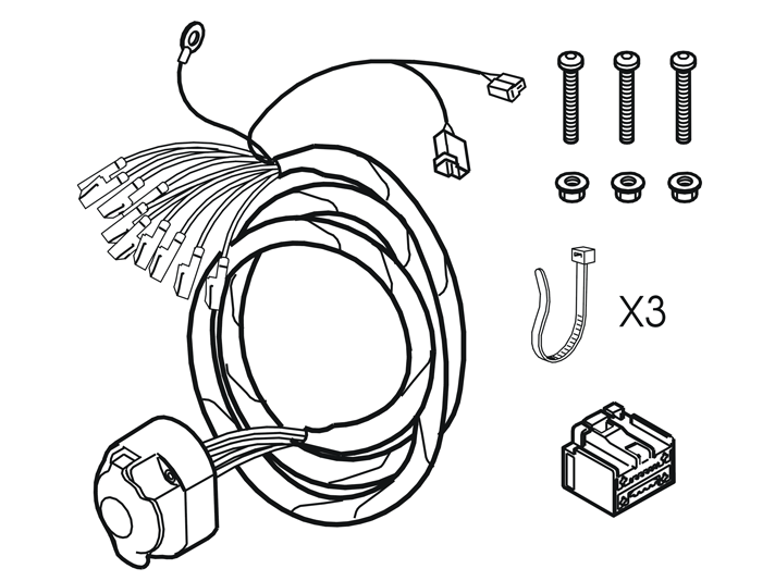
| | Installing trailer socket |
|  | | IMG-222064 |
|
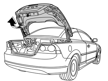
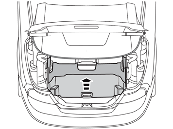
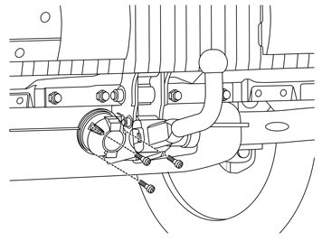
| | Installing trailer socket |
|  | | IMG-223800 |
|
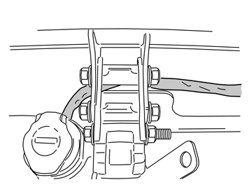
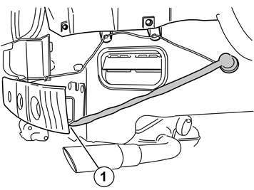
| | Route the cable harness between the body and the trailer hitch. Route it against the body's right side, on the underside of the bumper member's right attachment to the rubber leadthrough.
Note!
Note the routing of the cable harness at the centre of the towbar. |
Secure the cable harness on the trailer hitch with a cable tie.
|
|  | | IMG-222066 |
|
| | |
|  | | J8903624 |
|
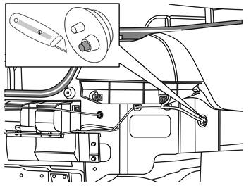
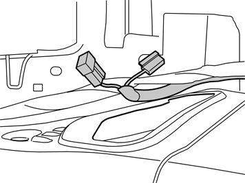
| | Use expander pliers and widen the hole in the rubber grommet. Pull the wiring through. |
|  | | IMG-224903 |
|
| | |
|  | | IMG-347737 |
|
| | |
|  | | IMG-359666 |
|
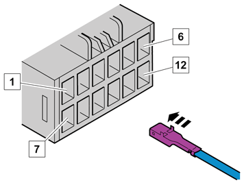
| | Position | Wiring | Function | 1 | Pink | Reversing lamp | 2 | | Not used | 3 | White | Ground | 4 | | Not used | 5 | Grey | Power supply | 6 | | Not used | 7 | Brown | Right parking lamps | 8 | Black | Left parking lamps | 9 | Green | Right indicator lamps | 10 | Yellow | Left indicator lamps | 11 | Red | Brake lamp | 12 | Blue | Fog lights |
|
|  | | IMG-227863 |
|
| | |
|  | | IMG-359969 |
|
| | |
|  | | IMG-359982 |
|
| | |
|  | | IMG-223842 |
|
| | |
|  | | IMG-223846 |
|
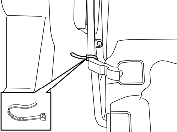
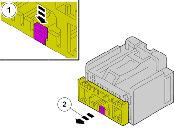
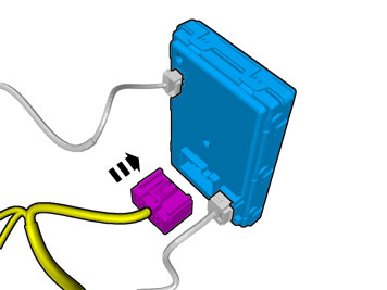
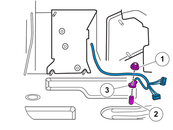
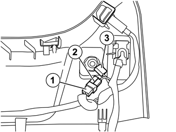
| | Remove the connector (1) on the 12 V socket of the sill panel and connect it to connector (2). Connect the connector (3) to the 12V socket. Secure the connectors (1) and (2) with a tie strap.
Reinstall the detached components in reverse order. |
|  | | IMG-348017 |
|
| | Note!
For correct function, the trailer module (TRM) must be programmed with software before checks can be carried out. |
Note!
To activate the trailer module (TRM) at least two light sources (lamps) must be connected. This can be done by connecting test equipment for the trailer connector or a trailer. |
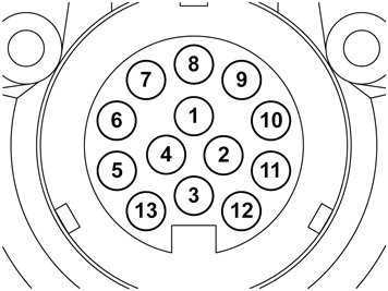
Position | Function | 1 | Left indicator lamps | 2 | Rear fog lamp | 3 | Ground | 4 | Right indicator lamps | 5 | Right rear running light | 6 | Brake lamp | 7 | Left rear running light | 8 | Tail lamp | 9 | Power supply | 10 | Charging | 11 | Charging Ground | 12 | Trailer indicator | 13 | Ground |
|