| | |
|  | | IMG-316263 |
|
| | |
|  | | IMG-342358 |
|
| | |
|  | | IMG-342359 |
|
| | |
|  | | IMG-342357 |
|
| | |
|  | | IMG-342360 |
|
| | |
|  | | IMG-341061 |
|
| | |
|  | | IMG-349232 |
|
| | |
|  | | IMG-341066 |
|
| | |
|  | | IMG-341067 |
|
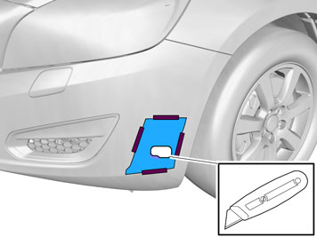
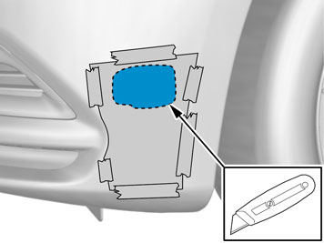
| | Note!
Cut carefully. It is easy to slip with the knife and move outside the template. |
Remove the template and tape pieces. Install the protective cover for the front engine block heater socket from the kit. Check that it aligns. Adjust the hole using a knife or file as necessary. Smooth off the hole edges. Remove any swarf.
|
|  | | IMG-349240 |
|
| | |
|  | | IMG-349237 |
|
| | |
|  | | IMG-349239 |
|
| | |
|  | | IMG-349241 |
|
| | |
|  | | IMG-349242 |
|
| | Note!
Cut carefully. It is easy to slip with the knife and move outside the template. |
Remove the template and tape pieces. Install the protective cover for the front engine block heater socket from the kit. Check that it aligns. Adjust the hole using a knife or file as necessary. Smooth off the hole edges. Remove any swarf.
|
|  | | IMG-341071 |
|
| | Applies to all vehicles Press the protective cover (from the kit) into place in the hole cut in the bumper cover. Take the cable for the front engine block heater socket with ground lead from the kit and thread them through the protective cover.
|
|  | | IMG-342364 |
|
|  | | IMG-342365 |
|
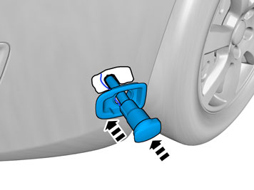
| | Illustrations A and B Install the attaching brace and nut from the kit. Rotate the connector for the front engine block heater socket carefully so that the cover opens backwards (Illustration B). Plug the electrical connector into the front engine block heater socket. Use the connector as a counterhold when tightening. Tighten the front engine block heater socket to the bumper shell.
|
|  | | IMG-340317 |
|
| | |
|  | | IMG-340576 |
|
| | |
|  | | IMG-341072 |
|
|  | | IMG-342366 |
|
| | |
|  | | IMG-231571 |
|
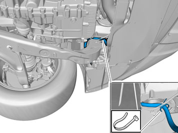
| | Drill a Ø 4mm (Ø 5/32 ") hole for the front intake grounding on the underside of the left front side member as illustrated. Deburr the hole edges, remove the drill swarf and apply rustproofing agent. Take a screw and toothed washer from the kit. Tighten the ground cable.
|
|  | | IMG-341074 |
|
| | |
|  | | IMG-279168 |
|
| | |
|  | | IMG-344072 |
|
| | |
|  | | IMG-231474 |
|
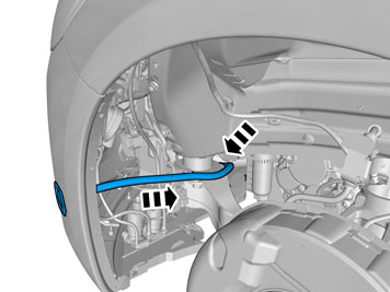
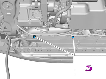
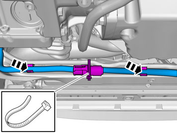
| | Detach the double clamp on the cable to the alternator that is located on the thermostat housing hose. Rotate the catch on the thermostat housing pipe anticlockwise. Detach the hose and drain the remaining coolant.
|
|  | | IMG-231475 |
|
| | Hint
Install a piece of tape over the cutting location and mark with a pen where the incision should be. Reinstall the hose connection in the pipe in order to support the cutting process. |
Note!
Do not damage the adjacent cable harnesses. |
|
|  | | IMG-231476 |
|
| | |
|  | | IMG-231477 |
|
| | Remove the short hose-end and press it on the pipe that runs to the thermostat housing. Make sure that the cut-out in the hose connection is turned down and fits into the corresponding pin in the pipe connection. Rotate the catch on the pipe clockwise against the stop. Take a hose clamp from the kit and install it on the hose-end.
|
|  | | IMG-231478 |
|
| | Take the engine block heater, bracket, rubber coated clamp and screw from the kit and assemble them as illustrated. Do not tighten the screw yet.
|
|  | | IMG-231479 |
|
| | |
|  | | IMG-231480 |
|
| | Position the engine block heater with bracket in the front edge of the oil sump and connect both hose-ends to the engine block heater's connections. Take a screw from the kit and tighten the bracket with engine block heater into the existing hole in the oil sump.
Note!
The screw is self-tapping so insertion may be slow. Make sure that the screw is centred straight into the hole, so that the screw head is flat against the bracket. |
|
|  | | IMG-231481 |
|
| | Now adjust the engine block heater in the rubber coated clamp so that the hoses are properly fitted on the engine block heater's connection. Tighten the screw to the rubber coated clamp. Tighten the hose clamps to the engine block heater. Install the double clamp to the cable for the alternator in the engine block heater's upper hose.
|
|  | | IMG-225580 |
|
| | Note!
Do not get any grease on the surfaces of the connector. |
|
|  | | IMG-231482 |
|
| | |
|  | | IMG-214063 |
|
| | |
|  | | IMG-344086 |
|
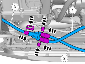
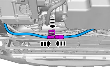
| | Applies when fitting passenger compartment connector at the same time Take the locking sleeves from the kit. Connect the cables in accordance with the following: Cable (1) from the engine block heater. Cable (2) joint cable to the passenger compartment connector socket. Cable (3) from the front engine block heater socket. Press the cables firmly into the junction connector and press the locking sleeves in over the cable splices.
|
|  | | IMG-344076 |
|
| | |
|  | | IMG-344077 |
|
| | |
|  | | IMG-342421 |
|
| | |
|  | | IMG-342422 |
|
| | |
|  | | IMG-342423 |
|
| | |
|  | | IMG-317784 |
|
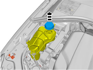
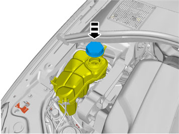
| | Fill with coolant, run the engine to operating temperature, bleed the cooling system and check that there are no leaks. Top up the cooling system as required.
|
|  | | IMG-341131 |
|
| | |
|  | | IMG-340577 |
|
| | |