|  | | IMG-332179 |
|
| | |
|  | | M8504883 |
|
| | |
|  | | M8504903 |
|
| | |
|  | | IMG-231614 |
|
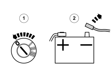
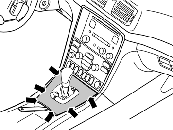
| | Turn the ignition key to position II. Engage the handbrake and move the gear selector lever towards the rear. Remove the two screws holding the bracket with the radio and dashboard environment panel in the centre console.
|
|  | | IMG-231615 |
|
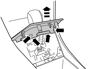
| | Remove the bracket with dashboard environment panel and the radio from the centre console: Pull the lower edge out and downwards until it releases from the mounting at the upper edge. Then fold backwards.
Note!
Do not damage the removed components or the surrounding panels. |
Remove the connectors. If the 12 pin gray terminal on the radio is not connected, the vehicle is equipped with an external amplifier. This information is used later in step 44.
|
|  | | M8502816 |
|
| | |
|  | | IMG-240984 |
|
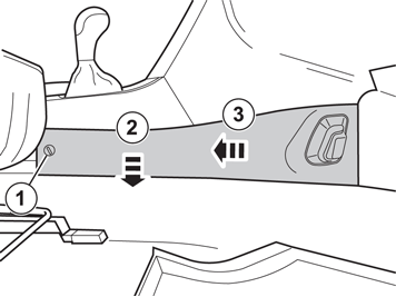
| | Turn the clip (1) a quarter turn anti-clockwise. Pull the panel out by the rear edge. Then pull the panel backwards until the hooks release. Remove the panel.
|
|  | | IMG-240985 |
|
| | |
|  | | IMG-242280 |
|
| | Applies to the S60 and V70 Open the glovebox. Lift the two hooks on each side past the lugs.
|
|  | | IMG-242281 |
|
| | |
|  | | IMG-242282 |
|
| | Applies to the S60 and V70 Remove: the eight screws. the connector for the glove box lighting. the connector for the foot well lighting. the glove box.
|
|  | | M8503917 |
|
| | |
|  | | D8502454 |
|
| | |
|  | | D8503430 |
|
| | Remove the weatherstrip (1) for the door at the A-pillar. Pull off the panel. Cut off the safety clip (2). Lift the panel upwards and inwards in the vehicle.
Note!
Ensure that the guide lugs on the panel do not scratch the dashboard. |
Turn the safety clip a quarter turn. Remove the safety clip.
|
|  | | R3501441 |
|
| | |
|  | | IMG-240986 |
|
| | |
|  | | IMG-240987 |
|
| | |
|  | | IMG-240988 |
|
| | |
|  | | IMG-240989 |
|
| | |
|  | | IMG-284125 |
|
| | Reinstall the ceiling panel and at the same time adjust the length of the cable. Clean the microphone and the headlining in the area illustrated, which corresponds to the size of the double-sided adhesive tape. Use a solution of 25% isoproanol and 75% water, as well as a lint free cloth. Dry with care, do not rub. Allow to dry.
Note!
In cases where the area is heavily soiled or treated with cockpit shine. First clean using a washing up detergent (FAIRY or similar). |
|
|  | | IMG-240991 |
|
| | |
|  | | IMG-240992 |
|
| | Pull the cable down along the A-pillar to the dashboard. Cut off 2 x 100x50mm pieces of foam tape in the middle. Secure the cable to the A-pillar using foam tape.
Caution!
The inflatable curtain (IC) is located inside the A-pillar panel, it is important that the cable is not positioned on it. |
|
|  | | IMG-240993 |
|
| | Route the cable along the lower side of the dashboard, to the center console. Install a new safety clip on the A-pillar panel.
Note!
It is important that a new safety clip is used when installing the A-pillar panel. |
Press the A-pillar panel into place. Reinstall the weatherstrip in the door opening.
Note!
It is important that the safety clip/hook and panel are correctly installed so that the SRS system is not affected. |
|
|  | | IMG-240994 |
|
| | |
|  | | IMG-240995 |
|
| | Lock the steering wheel in the lowest, rearmost position. Remove the rubber seal from the upper steering column cover by carefully prying off the hooks.
|
|  | | IMG-240996 |
|
| | Applies to the S60 and V70 Remove the combined instrument panel surround by carefully prying the lower edge so that the two clips release. Then pull the surround back until the three clips at the top edge release.
Note!
Do not damage the dashboard. |
|
|  | | D3800687 |
|
| | Applies to the S60 and V70 Remove the 4 x screws. Pull out the combined instrument panel without disconnecting the connector. Place the combined instrument panel to the left-hand side.
|
|  | | IMG-333484 |
|
| | Applies to the S60 and V70 File a cut-out for the cable in the surround.
|
|  | | IMG-333485 |
|
| | Applies to the S60 and V70 Take a 700 mm piece of foam tape and cut off 20 mm. Tape the long piece of foam tape on the cable, starting 50 mm from the control panel.
|
|  | | IMG-284204 |
|
| | Applies to the S60 and V70 Clean the area on the dashboard as illustrated, which corresponds to the size of the double-sided adhesive tape. Use a solution of 25% isopropanol and 75% water, as well as a lint free cloth. Dry with care, do not rub. Allow to dry.
Note!
In cases where the area is heavily soiled or treated with cockpit shine, first clean using a washing up detergent. |
|
|  | | IMG-333486 |
|
| | Applies to the S60 and V70 Remove the protective film from the tape on the reverse of the control panel. Align the control panel with the surround. The lower edge of the tape must be at the upper edge of the beveled section of the surround.
|
|  | | IMG-333487 |
|
| | Applies to the S60 and V70 Fold in and secure the cable on the reverse of the surround using the cut piece of tape (20 mm).
|
|  | | IMG-241002 |
|
| | Applies to the S60 and V70 Route the cable through the opening and pull it to the right of the center console. Reinstall the combined instrument panel. The cable must be above the combined instrument panel.
|
|  | | IMG-333488 |
|
| | Applies to the S60 and V70 Reinstall the surround and rubber seal.
|
|  | | IMG-241003 |
|
| | Applies to the S80 Make markings for the cable cut-out in the panel. Remove the cover panel (1) using a small screwdriver and the screws (2). Remove the panel by angling the upper edge outwards and pulling out. File the cut-out according to the markings.
|
|  | | IMG-332736 |
|
| | Applies to the S80 Tape a 700 mm long piece of foam tape on the cable, starting 70 mm from the control panel. |
|  | | IMG-241004 |
|
| | |
|  | | IMG-333489 |
|
| | Clean the area on the dashboard as illustrated, which corresponds to the size of the double-sided adhesive tape. Use a solution of 25% isopropanol and 75% water, as well as a lint free cloth. Dry with care, do not rub. Allow to dry.
Note!
In cases where the area is heavily soiled or treated with cockpit shine, first clean using a washing up detergent. |
|
|  | | IMG-333490 |
|
| | |
|  | | IMG-333491 |
|
|  | | IMG-333492 |
|
| | |
|  | | IMG-333493 |
|
| | |
|  | | IMG-241008 |
|
| | Connect the adapter cable's green and gray connector (1) to the vehicle's cable harness (2). Take a 700 mm piece of foam tape and cut into three pieces of the same length. Tape one piece around connector (1) and (2). Connector (3) is later connected to the stereo. Place the connected gray connector up to the left
Applies to cars with extra amplifier Take the gray connector located up to the left in the center console. Remove the foam tape. Disconnect the connectors and connect the 2 x grey adapter cable connectors. Reinstall the foam tape.
|
|  | | IMG-241009 |
|
| | Cut the protective casing for the cable harness with antenna cable, approximately 120 mm. Position the connected gray connector up to the left and the connected green connector at the bottom by the middle so that they are not obstructive when installing the radio.
|
|  | | IMG-241010 |
|
| | |
|  | | IMG-241011 |
|
| | |
|  | | IMG-239765 |
|
| | |
|  | | IMG-241012 |
|
| | |
|  | | IMG-241013 |
|
| | |
|  | | IMG-239778 |
|
| | |
|  | | IMG-241014 |
|
| | |
|  | | IMG-332181 |
|
| | Reinstall the detached components in reverse order. Turn the ignition key to position II. Reconnect the battery negative lead
|
|  | | IMG-331671 |
|
| | Carry out a function test as follows: Set the ignition switch to position I. Turn on the radio. Check that the control panel for Bluetooth lights up. Press the button (1) in the middle of the control panel. The radio should mute and a voice should be heard. Press the button (2). The voice should stop and the radio sound should return.
|


