| | Point - applies to the S80 |
|  | | D2000257 |
|
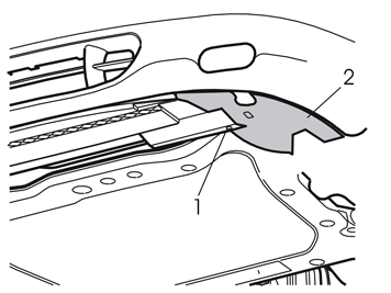
| | Point - applies to the S80 Raise the car Remove the screw (1) from the left air baffle (2) for the front brake Pull the left air baffle backwards. Remove the left air baffle Remove the right air baffle in the same way.
|
|  | | D2000431 |
|
| | |
|  | | D3603393 |
|
| | |
|  | | D3603394 |
|
| | |
|  | | D3601932 |
|
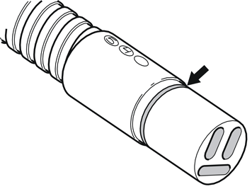
| | Note!
Do not get any grease on the contact surfaces of the connector. |
|
|  | | D3603395 |
|
| | |
|  | | D3603396 |
|
| | Note!
The large locking sleeve must be pressed over the connector on the cable from the front engine block heater socket. |
|
|  | | D3603397 |
|
| | Tighten the relay on the underneath of the side member. Use a screw from the kit in the same hole as the one in which the junction connector is positioned Connect the ground lead for the relay to the existing ground terminal at the front end of the side member. Tighten properly Secure the ground lead excess by the cable for the front engine block heater socket. Use the tie strap (1) from the kit.
|
|  | | D3603398 |
|
| | Tighten the single cable for the relay on top of the right front corner of the sub-frame. Tighten the cable together with the other wiring for the engine block heater/passenger
compartment connector socket Secure the single cable for the relay at the existing wiring. Use the tie strap (1) from the kit.
|
|  | | D2900448 |
|
| | |
|  | | R8504240 |
|
| | Turn the clips at the rear edge of the centre console 45°. Remove the right-hand side panel for the centre console (1). Pull the panel out at the rear edge and then straight back
Remove the soundproofing panel (2). Remove the three screws (3) first. Then pry the panel from the three clips on the rear side. Pull the panel backwards Remove the panel (4) from the right-hand front door sill by pulling the upper front edge backwards. Then pull the panel upwards to release all the clips.
|
|  | | D8703334 |
|
| | Remove the locking sleeve over the joint between the cable and the passenger compartment connector socket. Pull the cable off Remove the passenger compartment connector socket Push the carpet at the right-hand front seat to one side to access the lead-in to the engine compartment. It is located to the left at the lower edge of the soundproofing panel Move the rubber grommet with the cable to the engine compartment.
|
|  | | M8503476 |
|
| | |
|  | | A8504245 |
|
| | Insert your hand down the side of the lower section of the side cushion. Remove the left-hand side cushion Release the catches. At the same time lift the side cushion Place the cushion to one side.
|
|  | | M8503477 |
|
| | |
|  | | M8503481 |
|
| | |
|  | | M8503478 |
|
| | |
|  | | M8503479 |
|
| | |
|  | | M8503483 |
|
| | |
|  | | D2900449 |
|
|  | | D8200250 |
|
| | Cut the top off the large rubber cap on the recently routed rubber grommet for the cable harness Apply low temperature grease (P/N 1161417-9) to the rubber grommet to facilitate routing the cable to the passenger compartment connector socket Insert the cable for the passenger compartment connector socket. Insert the cable through the rubber grommet.
|
|  | | D3703333 |
|
| | Route both cables to the front edge of the sill on the right-hand front door Continue to route the single cable along the right-hand side of the car inside the floor carpets and insulation. Route the single cable to the accessory electronic module (AEM) located on
the right-hand side in the cargo compartment rear wheel well. Ensure that the single cable is positioned so that there is no risk of it catching or rubbing Secure at the cable duct in the cargo compartment. Use the three tie straps (1) from the kit.
|
|  | | D3703334 |
|
| | |
|  | | M3702529 |
|
| | Disconnect the large connector from the accessory electronic module (AEM). First press in the catch (A). Pull the locking handle (B) in the direction of the arrow until a click is heard
Pull the connector out from the control module.
|
|  | | M3702530 |
|
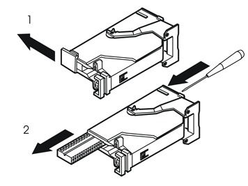
| | Remove the catch holding the switch in place in the connector. Pull the catch in the direction of the arrow Remove the switch by inserting a pointed object in the hole on the other end. Press the switch out.
|
|  | | M3702794 |
|
| | Note!
Number markings can be found on the top and bottom of the switch. The markings are very small. Ensure accuracy when installing the cable. |
|
|  | | M3702511 |
|
| | Reinstall the switch in the connector. Lock into place using the catch Press the connector into the control module and lock using the handle Press the control module into the bracket.
|
| | Reinstall the panels in the cargo compartment Reinstall the cargo compartment carpet Reinstall the sill trim panel in the rear door Reinstall the side cushion Reinstall the seat cushion Fold the backrest back into place Fold the front seat carpet back into place Connect the cable for the passenger compartment connector socket. Tighten the cable Reinstall the sill trim panel in the front door Reinstall the soundproofing panel and side panel for the centre console Reinstall the centre air baffle Reinstall the engine cover. Tighten the screws. Tighten to 24 Nm (18 lbf.ft) Reinstall the air baffles at the sides (if applicable) Program the software according to the service information in VIDA.
|
| | Point - applies to the XC90 |
|  | | R3501343 |
|
| | Point - applies to the XC90 |
|  | | R3501493 |
|
| | |
|  | | R2900268 |
|
| | Remove the junction connector together with the wiring from the underside of the plate underneath the headlamp. First remove the screw and the nut (1) Cut off the tie strap (2) Remove the locking sleeves over the cable splices on the junction connector. Disconnect the wiring Place the junction connector to one side. This will not be used again.
|
|  | | D3601932 |
|
| | Take the relay and the locking sleeves from the kit Lubricate the O-rings on the connectors for the relay and front engine block heater socket. Use low temperature grease, (P/N 1161417-9).
Note!
Do not get any grease on the contact surfaces of the connector. |
|
|  | | R2900255 |
|
| | Connect the cable (1) from the front engine block heater socket to the relay Connect the wiring for the engine block heater and passenger compartment connector socket to either socket (2) or (3) on the relay.
|
|  | | R2900256 |
|
| | Note!
The large locking sleeve must be pressed over the connector on the cable from the front engine block heater socket. |
|
|  | | R2900236 |
|
| | Position the wiring and relay on the under side of the plate (1). Position the relay with the side against the plate to release the switch Take a screw, washer and nut (2) from the kit. Tighten the relay to the plate Secure the cable for the front engine block heater socket at point (3) in the plastic lug for the bumper cover mounting Insert the thin cable together with the ground lead from the relay in the same position as the wiring for the engine block heater /passenger compartment connector socket Secure all wiring at point (4). Use a tie strap from the kit.
|
|  | | R8504142 |
|
| | Remove the right-hand side panel from the centre console. Pull off the panel starting at the front edge. Then pull backwards until all the clips release Remove the right-hand side soundproofing panel. First remove the two screws. Then pry off the panel at the top edge.
|
|  | | R8504241 |
|
| | |
|  | | R8504169 |
|
| | |
|  | | R8504170 |
|
| | Remove the sill trim panel for the right-hand front door. Pull it off, starting at the front edge, until the clip there has released. Continue backwards until the remaining clips have
released Unhook the sill trim panel from the B-post panel.
|
|  | | R8504171 |
|
| | |
|  | | R8504172 |
|
| | Fold the backrest on the right-hand seat in the second row forward as far as possible. Slide the front seat as far forward as possible. On cars with two rows of seats, the second row is
fixed Remove the cover (1) for the right rear seat mounting by prying off the rear edge.
|
|  | | R8504173 |
|
|  | | R8504174 |
|
| | Illustration A Applies to cars with two rows of seats On cars with two rows of seats the seat cannot be slid forwards. To remove the sill trim panel: First fold the backrest forwards when the rear edge of the sill trim panel is pulled off.
Then reposition the backrest to raise the seat cushion and provide more room to remove the sill trim panel. It is securely positioned. Do not damage the panel and surrounding components during
removal.
Illustration B |
|  | | R8902691 |
|
|  | | R8902931 |
|
| | Illustration A Applies to cars with two rows of seats Remove the two centre floor hatches. First lift them up slightly and then pull them loose from the mountings at the front edge.
If the rear centre floor hatch is equipped with a carrier bag holder on the lower side, the floor hatch is secured by a strap on each of the shorter sides of the storage box. These must be
removed. Illustration B Applies to cars with three rows of seats and integrated carrier bag holder on the underside of the centre floor hatch Fold up the centre rear floor hatch (1) Detach the two straps from the panel underneath. Lift up the rear edge of the panel. Fold the floor hatch back towards the panel and lift out the floor hatch and the panel.
Applies to cars with three rows of seats without an integrated carrier bag holder Lift up the centre rear floor hatch at the rear edge and lift it out.
|
|  | | R8504293 |
|
| | Applies to cars with two rows of seats Remove the front storage compartment.
|
|  | | R8504159 |
|
| | |
|  | | R3602949 |
|
| | Remove the screws for the passenger compartment connector socket. Remove the passenger compartment connector socket from the bracket inside the carpet Remove the locking sleeve. Disconnect the cable from the passenger compartment connector socket.
|
|  | | R8504295 |
|
| | |
|  | | R2000348 |
|
| | |
|  | | R2900253 |
|
| | |
|  | | R8600975 |
|
| | Disconnect the existing ground lead for the front engine block heater socket underneath the left-hand front member Route the ground lead to the relay. Connect both ground leads to the existing ground terminal.
|
|  | | R2900258 |
|
|  | | R2900261 |
|
| | Illustration A Pull off the cable and rubber grommet (1) for the passenger compartment connector socket Pull out the entire cable from the hole in the cowl panel. Remove the rubber grommet from the cable. A new rubber grommet is on the routed power supply cable.
Illustration B Cut the top off the new rubber grommet (1) Insert the cable for the passenger compartment connector socket through the new rubber grommet Lubricate the rubber grommet on the side facing inwards in the passenger compartment. Use low temperature grease (P/N 1161417-9) Adjust the wiring up to the grommet. Insert the wiring into the hole in the cowl panel Carefully route the rubber grommet into position from inside the passenger compartment by pulling the cable for the passenger compartment connector Clamp the power supply cable at the power steering pipe. Use a tie strap (2) from the kit.
|
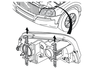
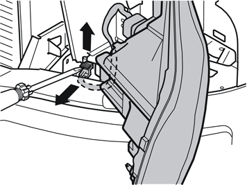
| | Reinstall the engine splash guard. Tighten the screws. Tighten to 25 Nm (18 lbf.ft.) Connect the connector to the headlamp. Reinstall the headlamp. Ensure that the headlamp lock pins are correctly positioned: The short innermost and the long wide outside pins.
|
|  | | R3702904 |
|
| | Insert the cable harness between the carpet and the door sill towards the floor as far as it will go. Route it along the right-hand side of the car up to the opening for the right-hand
rear door Pull the cable up to the right-hand seat mounting on the right-hand seat in the second row of seats Pull away the carpet from the front edge of the right-hand side panel in the cargo compartment Route the cable to the right-hand side of the air duct towards the front edge of the rear wheel arch. Clamp the cable at the air duct. Use two tie straps (1) from the kit Route the cable along the reverse of the air duct and out along the front edge of the wheel arch.
|
|  | | R3702907 |
|
|  | | R3703023 |
|
| | Applies to cars with three rows of seatsIllustration A Illustration B |
|  | | R3702935 |
|
| | Applies to cars with two rows of seats Route the cable along the left-hand side of the seat belt mounting at the front edge of the wheel arch. Route the cable inside the carpet at the front edge of the side panel, between the
side panel and the cargo floor support, to the accessory electronic module (AEM).
|
|  | | R3702881 |
|
| | |
|  | | R3702909 |
|
| | Disconnect the large connector from the accessory electronic module (AEM). First press in the catch (A). Pull the black locking handle (B) in the direction of the arrow until a click is
heard. Disconnect the connector Disconnect the connector from the accessory electronic module.
|
|  | | M3702530 |
|
| | Remove the black catch holding the black switch in place in the connector. Pull the catch in the direction of the arrow Remove the black switch. Insert a pointed object in the hole on the other end of the connector. Press the switch out.
|
|  | | M3702794 |
|
| | Note!
The numerical markings can be found on the top and bottom of the connector. However, the markings are extremely small so take care when installing the cable. |
|
| | Reinstall the black switch in the connector. Lock into place using the catch Press the connector into the accessory electronic module (AEM). Secure using the black locking handle Reinstall the accessory electronic module (AEM) and the bracket. Clamp the wiring. Use the tie strap from the kit Reinstall the folding panel on the right-hand side in the cargo compartment Reinstall the right-hand side floor hatch Reinstall the storage boxes Reinstall the rear floor hatch(es) Reinstall the carpet at the front edge of the right-hand side panel Reinstall the sill trim panels in the doors on the right-hand side. Reinstall the panel over the cable splice between them Reinstall the panel and cover on the right-hand mountings on the right-hand seat on the second row of seats Reinstall the panel on the right rear mounting of the right-hand front seat Fold the carpet back on the right front side Reinstall the passenger compartment connector socket Reinstall the soundproofing panel. Reinstall the right-hand side panel on the centre console Program the software according to the service information in VIDA.
|

