| | Preparations Note!
AEM adapted parking assistance. |
Note!
This accessory requires software unique to the car. |
Note!
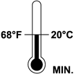
During installation the underlying surface must be kept at a temperature of at least +15°C (60°F). |
|
| | Turn the ignition switch to position 0. Remove the ignition key from the ignition switch. Disconnect the battery negative lead.
Note!
Wait at least one minute before unplugging the connectors or removing other electrical equipment. |
Clean the rear bumper. Use a mild soap solution.
|
|  | | D8502339 |
|
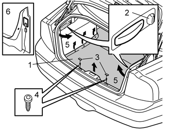
| | Place the floor mat carpet to one side (1) in the luggage compartment. Turn the clip (2) on the side panels. Remove the clip by pressing in its centre. Remove the plastic nut at the rear edge of the panels and remove the side panels. Remove the covers (3) and the screws (4) from the sill panel. Grasp the outer edges (5) of the sill panel and pull inwards towards the centre so that the clips release from the sides. Disconnect the connectors (6) for the luggage compartment lamps. Remove the sill trim panel. Pull the sill trim panel straight upwards so that the clips release from the rear cross member.
|
|  | | D8100911 |
|
| | |
|  | | D8601151 |
|
| | Raise the car. Remove the rear wheels. Carefully drill out the pop rivets holding the bumper cover on both sides. Use a Ø6 mm (15/64") diameter drill bit.
Note!
Only drill out the upper and lower pop rivets. |
Twist the drill back and forth and try to stop the rivet from rotating. Use a thin bladed screwdriver and insert it in the pop rivet to prevent it rotating.
Note!
Do not damage the plastic components. |
|
|  | | D8601152 |
|
| | |
|  | | D8600315 |
|
| | |
|  | | M8903300 |
|
| | Remove the outer striker plates (1). Depress the lower catches (2). Remove the foam from the bumper cover.
Note!
Do not remove the antenna from the foam. |
Clean the bumper cover internally.
|
| | |
|  | | D8601198 |
|
| | Installing sensors Pre-drill the holes through the centre of the markings (1). Use a 3 mm (1/8”) diameter drill bit. Drill from the inside of the bumper cover. Drill out the holes. Use a 8.5 mm (21/64") diameter drill bit.
|
|  | | IMG-404910 |
|
| | Enlarge the holes in the bumper cover with hole tool 31 mm. Insert the tool's cutting part on the outside of the bumper cover. Turn the cutting part so that its shape follows the shape of the bumper. This is so not to crush the bumper cover unnecessarily. Screw the hole tool together until it has cut the hole in the bumper cover. Remove the plastic pieces from the hole tool and make the remaining holes in the same way.
|
|  | | M3603452 |
|
| | Take sensors and their holders from the kit. Clean sensors and holders with a cleaning serviette, P/N 9192678, and leave to dry. Apply a thin layer of activator, P/N 8637076, over the sensors and holders.
Note!
Only paint the parts that are visible after installation. |
|
|  | | D8600320 |
|
| | |
|  | | A3601751 |
|
| | |
|  | | A3601752 |
|
| | Remove the yellow protective tape from one side of the tape. Secure the tape on the sensor holder Carry out the procedure above for the three remaining sensor holders.
|
|  | | D8600321 |
|
| | Remove the orange protective film from the pieces of tape on the sensor holders Install the holders for the sensors. The narrow side must be pointing upward. Install horizontally in line with the bumper cover, as illustrated.
Note!
The tape adheres immediately. |
Caution!
Incorrect positioning of the sensors may result in partial or complete malfunction. |
|
|  | | D8601210 |
|
| | |
|  | | D8601211 |
|
| | Apply activator to the underneath of the moulding in the bumper cover where the cable harness is to be attached. Secure the cable harness properly using butyl tape. Reinstall the foam and secure with all the clips.
|
|  | | D3904840 |
|
| | |
|  | | D8601213 |
|
| | Position the bumper so that sensors can be painted. Ensure that backing paper covers the area around the sensor holes.
Note!
Take care to ensure that the activator has dried, at least ten minutes, before the paint is sprayed on. |
Spray the sensors and cradles using the same colour code paint as the car. Use paint recommended by Volvo. Paint a maximum of two coats of paint.
Caution!
Too many layers of paint may result in partial or complete malfunction. |
|
|  | | D8601157 |
|
| | Lift the bumper into position Pull the cable harness for the sensors through the hole for the left guide of the bumper and pull in the cable. Reinstall the antenna connector Reinstall the bumper by aligning the guides (1) and pushing.
Note!
Ensure that the cable harness for the sensors is not trapped. |
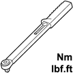
Pull in the cable harness. Reinstall the nuts. Torque tighten to 18 Nm (13 lbf.ft.) Install the seal over the nuts.
|
|  | | D8601153 |
|
| | Engage all bumper cover hooks. Secure the inner wing on the bumper cover by pop riveting the wing on both sides. Reinstall the wheels. Torque tighten to 140 Nm (105 lbf.ft.).
|
| | Installation of the Parking Assistance Module (PAM) |
|  | | D3904974 |
|
| | Installation of the Parking Assistance Module (PAM) |
|  | | D3904975 |
|
| | |
|  | | D8903603 |
|
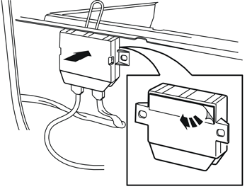
| | Clean the vertical panel surface under the member where the control module will be located. Use a mixture of 30% windscreen washer fluid and 70% water Apply activator to the panel surface under the member Allow the activator to dry completely, for at least 10 minutes.
|
|  | | D3904844 |
|
| | Remove the backing from the tape on the Velcro strap for the control module. Secure the control module to the activator covered panel surface below the member Press the tape on the Velcro strap hard so that the adhesive bonds.
|
| | |
|  | | D8502224 |
|
| | |
|  | | D8502684 |
|
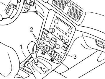
| | Move the gear selector lever to the rear position. Pull the panel (1) with the gaiter backward, as far as possible. Remove the screws (2) from the dashboard environment panel (3).
|
|  | | D8503412 |
|
| | Carefully angle the dashboard environment panel using a weatherstrip tool, so that the short side of the dashboard environment panel can be gripped with a couple of fingers. Remove the dashboard environment panel by pulling it straight down while maintaining the angle. The panel is fitted securely, so some force is required to remove it. Disconnect the connectors on the reverse of the dashboard environment panel. Place the dashboard environment panel to one side.
Note!
If any of the outer hooks fail then this must be rectified. See the section on the dashboard in the Workshop Manual in VIDA. |
|
|  | | M8503159 |
|
| | Note!
The surround with three button places must be replaced with a surround with seven button places if necessary. This can be purchased separately. |
|
|  | | D8502226 |
|
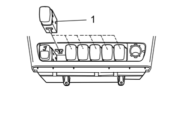
| | Remove the dummy button and install the new switch (1) in any available position. Reinstall the surround and 12V socket. Connect the connectors to the dashboard environment panel. Reinstall the dashboard environment panel. Reinstall the cover panel in front of the gear selector lever.
|
| | |
| | Finishing work Reinstall the panels in reverse order. Reconnect the battery negative lead Remove the protective paper from the bumper. Program the software in accordance with the service information in VIDA Check the function of the parking assistance. Check that it can be turned off using the button in the climate panel.
Caution!
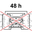
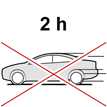
Leave the car indoors for 2 hours after carrying out the work. Do not wash the car for 48 hours. |
|


