2006 D5 AUTOMATIC L.H.D

Monteringsveiledning

Installation instructions, accessories
Volvo Car Corporation Gothenburg, Sweden
S80 2006
S80 (-06) 2006

Instruction NoVersionPart. No.Click to download PDF-version of this Installation Instruction
91724251.0
Protective panel


D2000260


Equipment
A0000162
A0000161

D2000261

MA Reacção
Tem comentários a fazer sobre esta publicação? Contacte o concessionário mais próximo. Agradecemos a sua colaboração!

Publicação #: MA 9172425, Publicação: 2000-05

Observações:.......................................................................................................

............................................................................................................................

............................................................................................................................

............................................................................................................................

............................................................................................................................

.............................................................................................................................

De:.......................................................................................................................

Morada:.............................................................................................................

# telefone:....................................................................................................

Telefax:...............................................................................................................


INTRODUCTION

  • Read through all of the instructions before starting installation.

  • Notifications and warning texts are for your safety and to minimise the risk of something breaking during installation.

  • Ensure that all tools stated in the instructions are available before starting installation.

  • Certain steps in the instructions are only presented in the form of images. Explanatory text is also given for more complicated steps.

  • In the event of any problems with the instructions or the accessory, contact your local Volvo dealer.

1
D2000285
 

Applies to diesel engine cars

On diesel engine cars, the left-hand air baffle must not be used.

  • Turn the protective panel around

  • Drill out the four pop rivets (1). Remove the air baffle

  • Remove the drill and rivet swarf.

2
D2000258
 

  • Raise the car

  • Remove the air baffle (1) by slackening off the screws (2).

3
M2000406
 

  • Lift up the protective panel towards the sub-frame. Install the small screws in the front holes (1). At the same time, position the washer between the sub-frame and the protective panel in the right-hand hole. Loosely screw the screws into place

  • Position the sleeve between the protective panel and the sub-frame by the hole (2). Screw the long screw into place.

4
M2000405
 

  • Secure the nuts on two of the large washers. Use two small pieces of butyl tape. This makes it easier to position the nuts, opposite the holes on the inside of the sub-frame.

5
M2000407
 

    Applies to the left-hand rear mounting on diesel engine cars and the vibration damper in the rear profile in the sub-frame

  • Insert the nut and washer in the space on the left-hand side of the vibration damper. In order for the nut and washer to pass the vibration damper, the nut must be repositioned slightly on the washer. The nut and washer will pass the vibration damper if they are positioned as illustrated.

6
M2000408
 

    Applies to the left-hand rear mounting on diesel engine cars and the vibration damper in the rear profile in the sub-frame

  • Move the nut and washer over the hole in the sub-frame. If the position of the nut has changed in relation to the hole in the washer, insert a finger or an angled, thick metal wire in the small hole in the sub-frame. Secure the washer. Centre the nut over the hole in the washer.

7
D2000262
 

  • Position the nuts (1) and the washers (2) above the rear holes in the sub-frame. Position the washers (3) between the sub-frame and the protective panel. Loosely screw the screws (4) into place

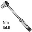
  • Tighten the front screws (5). Tighten to 25 Nm (19 lbf. ft.)

  • Tighten the rear screws (4). Tighten to 50 Nm (38 lbf. ft.)

  • Post-tighten the screws after approximately 1 minute so that the materials have time to settle.