| | |
| | Read through all of the instructions before starting installation. Notifications and warning texts are for your safety and to minimise the risk of something breaking during installation. Ensure that all tools stated in the instructions are available before starting installation. Certain steps in the instructions are only presented in the form of images. Explanatory text is also given for more complicated steps. In the event of any problems with the instructions or the accessory, contact your local Volvo dealer.
|
| | |
| | When installing, the car must retain a temperature of 20 degrees C. |
| | |
|  | | IMG-363036 |
|
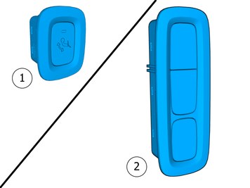
| | Note!
This colour chart displays (in colour print and electronic version) the importance of the different colours used in the images of the method steps. |
Used for focused component, the component with which you will do something. Used as extra colors when you need to show or differentiate additional parts. Used for attachments that are to be removed/installed. May be screws, clips, connectors, etc. Used when the component is not fully removed from the vehicle but only hung to the side. Used for standard tools and special tools. Used as background color for vehicle components.
|
| | Disconnecting the battery |
|  | | IMG-394535 |
|
| | |
|  | | IMG-394779 |
|
| | |
|  | | IMG-387004 |
|
| | |
|  | | IMG-394520 |
|
| | Remove the battery's negative cable. |
| | |
|  | | IMG-398662 |
|
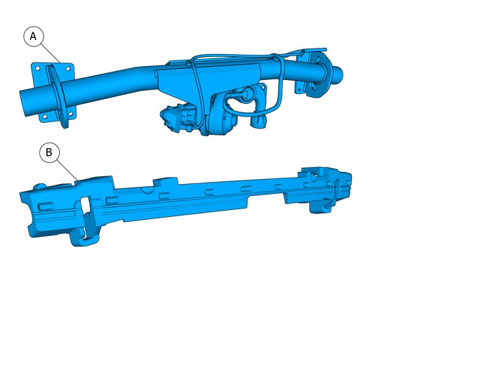
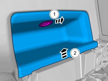
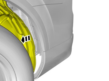
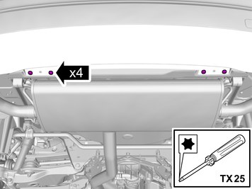
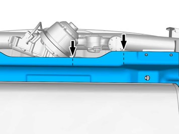
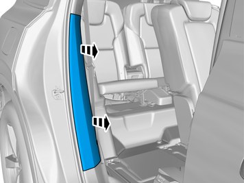
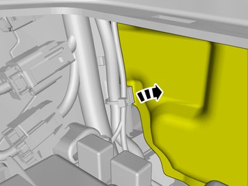
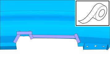
| | Make sure that the components are not mixed up at the installation. Remove the marked part. Repeat on the other side. |
|  | | IMG-403002 |
|
| | |
|  | | IMG-385738 |
|
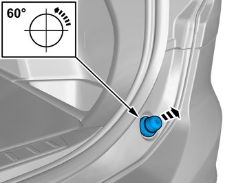
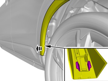
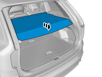
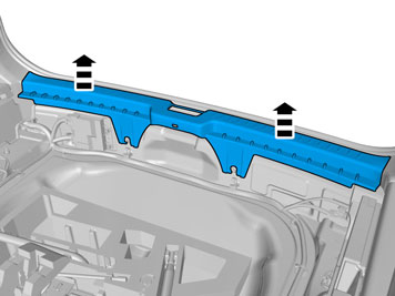
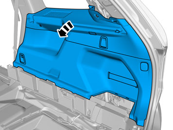
| | Fold the wing liner aside. Repeat on the other side. |
|  | | IMG-402988 |
|
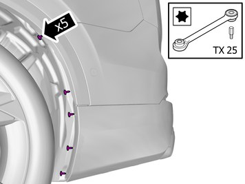
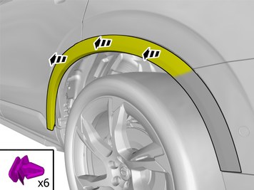
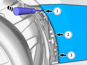
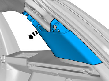
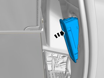
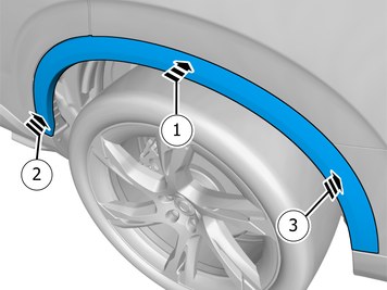
| | Remove the part carefully Release the catches. |
|  | | IMG-402987 |
|
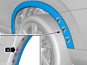
| | Remove the part carefully Loosen the clips. |
|  | | IMG-402986 |
|
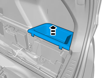
| | Remove the part carefully Remove the marked part. |
|  | | IMG-401258 |
|
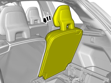
| | Release the catches. Remove the part carefully |
|  | | IMG-392800 |
|
| | |
|  | | IMG-398711 |
|
| | |
|  | | IMG-377070 |
|
| | Repeat the steps when removing on opposite side. |
|  | | IMG-381918 |
|
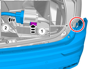
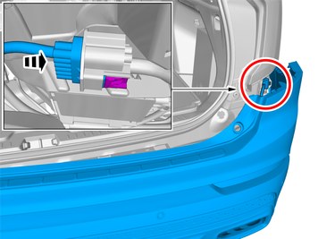
| | Locate the connector. Release the connector's catch. Disconnect the connector. |
|  | | IMG-398676 |
|
| | |
|  | | IMG-381867 |
|
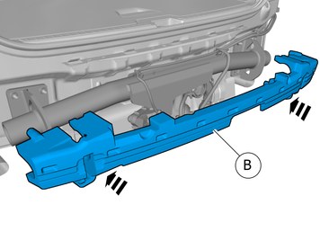
| | Caution!
Place the Bumper Cover on a suitable surface. |
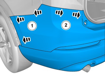
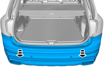
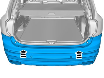
Request the aid of a colleague for this procedure. Remove the marked part. |
|  | | IMG-381872 |
|
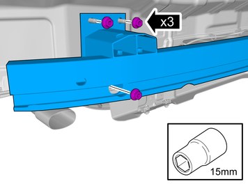
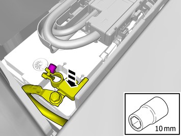
| | Remove the nuts. The part is to be reused. Repeat on the other side. |
|  | | IMG-381912 |
|
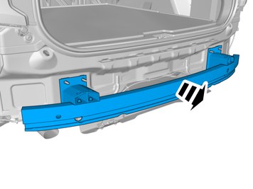
| | The part is not to be reused. |
| | |
|  | | IMG-381873 |
|
| | Note!
This step is easier with two people. |
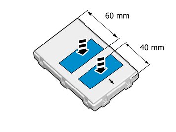
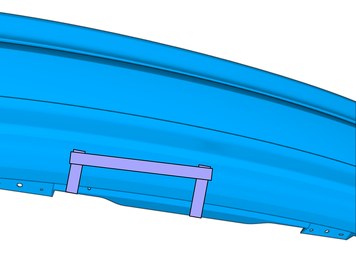
Install component that comes with the accessory kit. |
|  | | IMG-472862 |
|
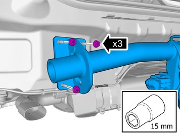
| | Install the nuts Repeat on the other side. |
| | |
|  | | IMG-405908 |
|
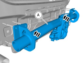
| | Install component that comes with the accessory kit. Repeat on the other side. |
|  | | IMG-405909 |
|
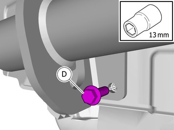
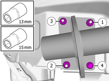
| | Tighten the nuts. Tighten the screw.
Tightening torque: Tow hitch member mounting to body frame
Stage 1:
50 Nm
Stage 2:
30 Degree
Repeat on the other side. |
| | Vehicles without weld nut |
|  | | IMG-386120 |
|
| | Install the screw. Repeat on the other side. |
|  | | IMG-386113 |
|
| | Install the nut. Repeat on the other side. |
|  | | IMG-399383 |
|
| |
Tightening torque: Tow hitch member mounting to body frame
Stage 1:
50 Nm
Stage 2:
30 Degree
Repeat on the other side. |
| | |
|  | | IMG-405695 |
|
| | |
| | |
|  | | IMG-396670 |
|
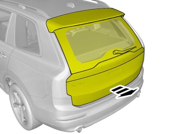
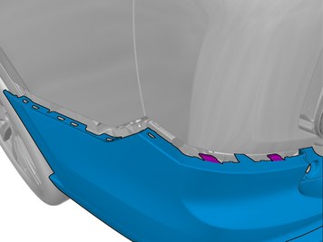
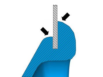
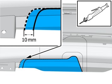
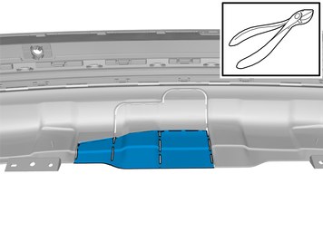
| | Cut following the dotted lines. |
|  | | IMG-396690 |
|
| | |
|  | | IMG-396700 |
|
| | |
|  | | IMG-395013 |
|
| | |
| | |
|  | | IMG-405677 |
|
| | Install component that comes with the accessory kit. Locate relevant marking. Position/route the cable harness as illustrated. Install the wiring harness. |
|  | | IMG-405672 |
|
| | Install component that comes with the accessory kit. |
| | |
|  | | IMG-383040 |
|
| | |
|  | | IMG-394727 |
|
| | |
| | Vehicles with TV-receiver |
|  | | IMG-383039 |
|
| | |
|  | | IMG-383043 |
|
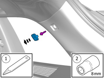
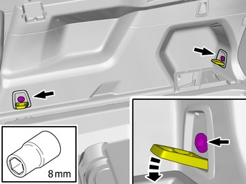
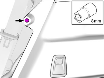
| | Remove the marked part. Remove the screw.
Tightening torque: Panel, to D-Pillar
, 4.5 Nm
|
|  | | IMG-383044 |
|
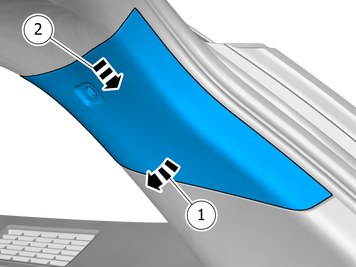
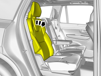
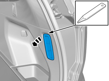
| | Remove the panel. Check that the fasteners are undamaged before installation. If not, they must be replaced with new ones. |
|  | | IMG-383045 |
|
| | |
|  | | IMG-383046 |
|
| | |
| | Vehicles with seven seats |
|  | | IMG-401374 |
|
| | |
| | Vehicles with TV-receiver |
|  | | IMG-383042 |
|
| | |
|  | | IMG-383047 |
|
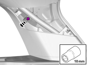
| | Note!
Do not loosen the bolts more than 2 turns. |
|
|  | | IMG-383048 |
|
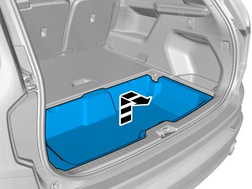
| | Remove the panel. Check that the fasteners are undamaged before installation. If not, they must be replaced with new ones. |
|  | | IMG-383066 |
|
| | |
|  | | IMG-393945 |
|
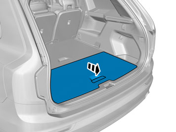
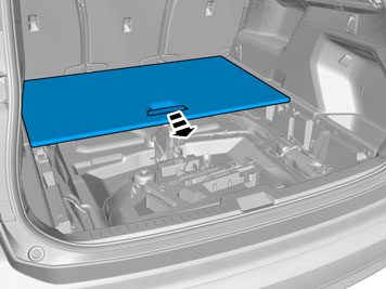
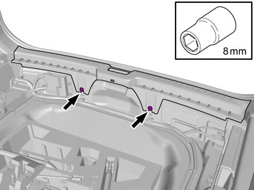
| | Remove the screws.
Tightening torque: Cargo anchor, to body
, 13 Nm
|
|  | | IMG-397295 |
|
| | |
|  | | IMG-404384 |
|
| | |
|  | | IMG-396625 |
|
| | |
| | Vehicles with air suspension |
|  | | IMG-398660 |
|
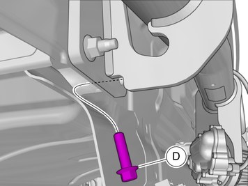
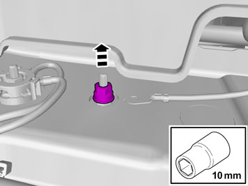
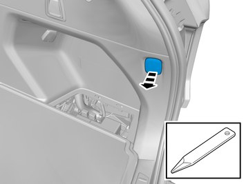
| | Loosen the component indicated. Do not remove it. Use: Interior trim remover
|
|  | | IMG-398661 |
|
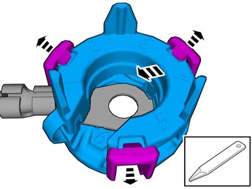
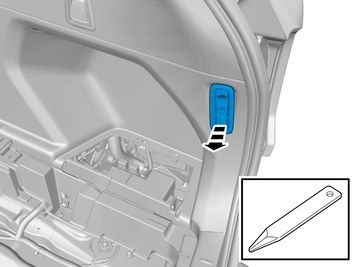
| | Disconnect the connector. |
| | Vehicles with TV-receiver |
|  | | IMG-383049 |
|
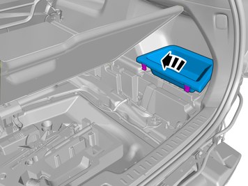
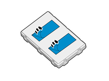
| | Note!
The number of connectors may vary depending on the vehicle's equipment level. |
Detach the panel. Disconnect the connectors. |
|  | | IMG-415430 |
|
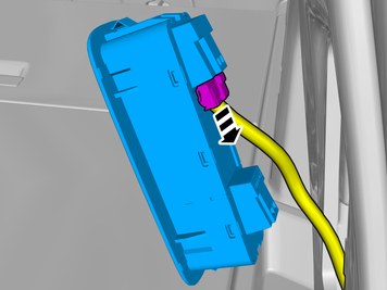
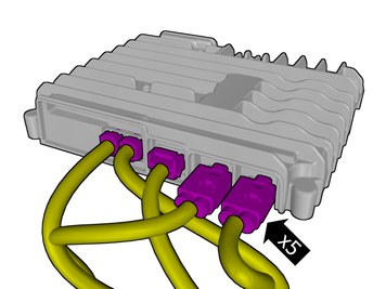
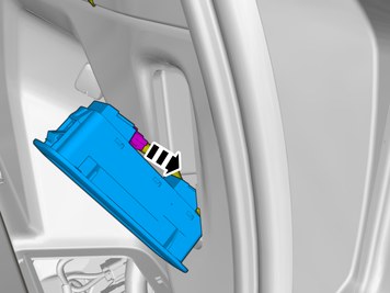
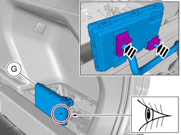
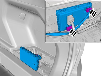
| | Note!
The graphic shows the back of the component before removal. |
Disconnect the connectors. |
|  | | IMG-415461 |
|
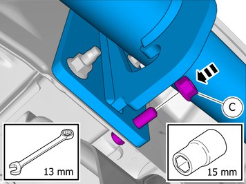
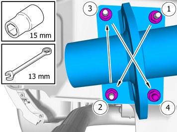
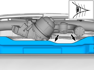
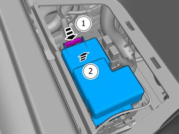
| | Remove the screws. Remove the nut. Lift the marked component up |
| | Applies to all other vehicles |
|  | | IMG-385727 |
|
| | |
|  | | IMG-385513 |
|
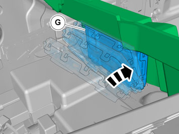
| | Release the catch. Remove the marked part. |
|  | | IMG-385592 |
|
| | Fold the insulation aside. |
|  | | IMG-385593 |
|
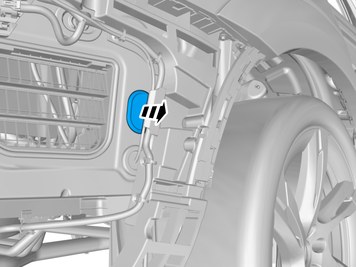
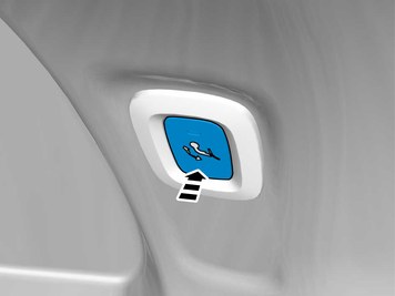
| | Locate the rubber grommet under the insulation and press it out. |
|  | | IMG-385583 |
|
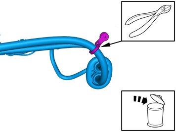
| | Remove the marked part. The part is not to be reused. |
| | |
| | Vehicles manufactured before 2022w22 |
|  | | IMG-483482 |
|
| | Caution!
Ensure that the cable/cables are not damaged. |
Remove the marked part. The part is not to be reused. |
|  | | IMG-483485 |
|
| | Install component that comes with the accessory kit. |
|  | | IMG-405697 |
|
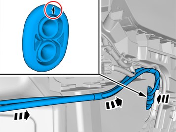
| | Route the wiring harness into the passenger compartment. |
|  | | IMG-358177 |
|
| | Caution!
Make sure that the rubber grommet seals properly to the body. |
|
|  | | IMG-483484 |
|
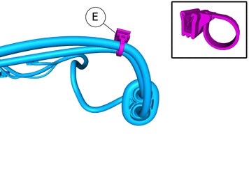
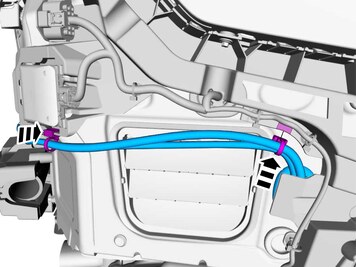
| | Fasten the wiring harness using the existing clips. |
| | Vehicles manufactured from 2022w22 |
| 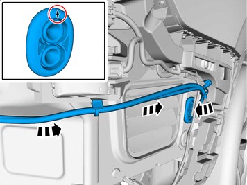 | | IMG-483486 |
|
| | Route the wiring harness into the passenger compartment. |
| | | IMG-358177 |
|
| | Caution!
Make sure that the rubber grommet seals properly to the body. |
|
|  | | IMG-483487 |
|
| | Fasten the wiring harness using the existing clips. |
| | |
|  | | IMG-385805 |
|
| | |
|  | | IMG-386982 |
|
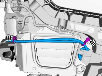
| | Route the cable harness to the existing cable harness. Tighten the cable tie. |
|  | | IMG-383079 |
|
| | Ground connection Remove the nut. The part is to be reused. |
|  | | IMG-406084 |
|
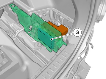
| | Note!
This step is only necessary if the component in the graphic is included in the accessory kit. |
Release the locks. Remove the marked part. The part is not to be reused. |
|  | | IMG-381883 |
|
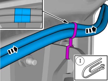
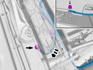
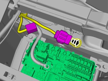
| | Position/route the cable harness as illustrated. |
|  | | IMG-383080 |
|
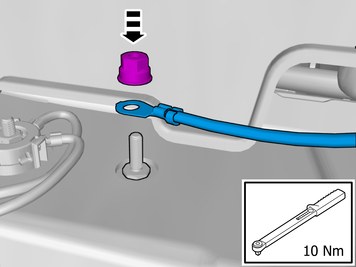
| | Connect the prerouted cable. Tighten the nut.
Tightening torque: M6
, 10 Nm
|
| | |
|  | | IMG-392436 |
|
| | |
| | |
| | |
|  | | IMG-381884 |
|
| | Remove the marked part. The part is not to be reused. |
| | |
|  | | IMG-386369 |
|
| | Remove the marked part. The part is not to be reused. |
|  | | IMG-386414 |
|
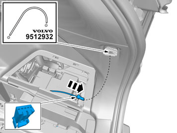
| | Disconnect the connector. The part is not to be reused. |
| | |
|  | | IMG-381908 |
|
| | Pull the wiring through.
Use special tool: T9512932, Tension spring
|
| | |
|  | | IMG-381887 |
|
| | |
|  | | IMG-381888 |
|
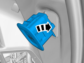
| | Install component that comes with the accessory kit. |
| | |
|  | | IMG-386446 |
|
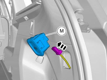
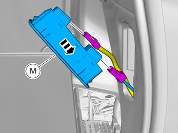
| | Connect the connector. Connect the prerouted cable. |
|  | | IMG-386463 |
|
| | Install component that comes with the accessory kit. |
| | |
|  | | IMG-382156 |
|
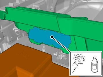
| | Clean the surface. Use: 1161721, Isopropanol
Wipe dry. |
|  | | IMG-385629 |
|
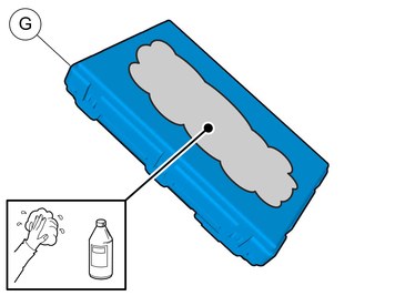
| | Clean the surface. Use: 1161721, Isopropanol
Wipe dry. |
|  | | IMG-222282 |
|
| | |
|  | | IMG-241925 |
|
| | |
|  | | IMG-392341 |
|
| | |
|  | | IMG-386383 |
|
| | Connect the prerouted cables. |
|  | | IMG-396797 |
|
| | Locate the pre-routed connectors. Disconnect the connector, if applicable. The part is not to be reused. |
|  | | IMG-386391 |
|
| | |
|  | | IMG-392282 |
|
| | |
|  | | IMG-356352 |
|
| | Remove the protective film. |
|  | | IMG-381889 |
|
| | Install component that comes with the accessory kit. |
|  | | IMG-493634 |
|
| | Install component that comes with the accessory kit. |
|  | | IMG-493635 |
|
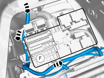
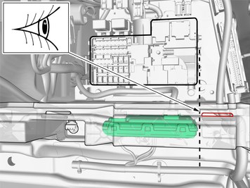
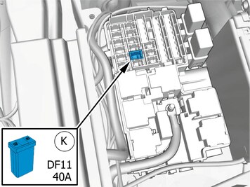
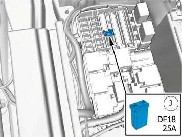
| | Note!
If position DF18 is occupied, ensure that a 40A fuse is mounted. |
Install component that comes with the accessory kit. |
| | |
| | Vehicles manufactured before 2022w22 |
|  | | IMG-396705 |
|
| | |
|  | | IMG-403685 |
|
| | |
|  | | IMG-387040 |
|
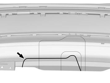
| | Apply tape to the other side, opposite the marking lines. |
|  | | IMG-397076 |
|
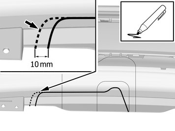
| | Remove the marked part. Use: Air-powered air saw
|
|  | | IMG-387038 |
|
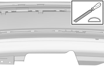
| | Deburr edges Remove the tape. |
| | Vehicles manufactured from 2022w22 |
|  | | IMG-483488 |
|
| | |
|  | | IMG-483491 |
|
| | Apply tape to the other side, opposite the marking lines. |
|  | | IMG-483489 |
|
| | Remove the marked part. Use: Air-powered air saw
|
|  | | IMG-483490 |
|
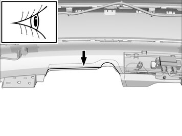
| | Deburr edges Remove the tape. |
| | Vehicles with skidplate (accessory) |
|  | | IMG-400604 |
|
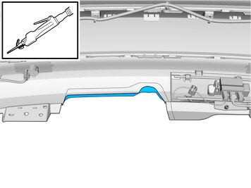
| | Cut following the dotted lines. |
| | |
|  | | IMG-395285 |
|
| | Request the aid of a colleague for this procedure. Connect the connector. |
|  | | IMG-395286 |
|
| | Reinstall the bumper. Request the aid of a colleague for this procedure. |
|  | | IMG-402997 |
|
| | Note!
Make sure to follow the sequence indicated. |
Reinstall the removed part. Ensure that all clips engage. |
| | Reinstall the removed parts in reverse order. |
| | |
|  | | IMG-394580 |
|
| | Reinstall the battery's negative cable.
Tightening torque: Battery cable for battery
, 6 Nm
|
|  | | IMG-242268 |
|
| | Download software (application) for the accessory's function according to the service information in VIDA. Order and download software according to: 30644822
|
| | |
|  | | IMG-414730 |
|
| | |
|  | | IMG-414300 |
|
| | |
|  | | IMG-421548 |
|
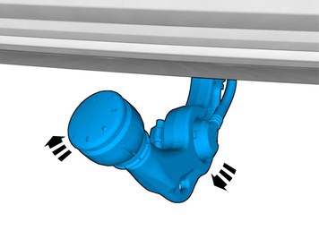
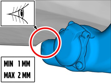
| | If the components rub against each other, adjustments must be made to correct this. |
|  | | IMG-348017 |
|
| | Warning!
Check for correct operation after the installation. |
Note!
To activate the trailer module (TRM) at least two light sources (lamps) must be connected. This can be done by connecting test equipment for the trailer connector, or a trailer. |
Note!
The trailer module (TRM) must be programmed with correct software to function correctly. |
Left indicator lamp Fog tail lamps. Ground connection Right indicator lamp Right position lamp Brake light Left position lamp Back-up lamp Battery voltage, constant Battery voltage, ignition on Ground connection Not connected Ground connection
|
| | | IMG-414730 |
|
| | |
|  | | IMG-414301 |
|
| | |