| | |
|  | | IMG-247309 |
|
| | |
|  | | IMG-239420 |
|
| | |
|  | | IMG-249172 |
|
| | |
|  | | IMG-222267 |
|
| | |
|  | | IMG-231433 |
|
| | |
|  | | IMG-222268 |
|
| | |
|  | | IMG-225205 |
|
| | |
|  | | IMG-225201 |
|
| | |
|  | | IMG-239483 |
|
| | Move the carpeting aside. Make a cut in the thick insulating mat starting level with the blue connector of the central electronic module (CEM) and then continue straight down. Move aside the insulating mat to access the grommet.
|
|  | | IMG-249173 |
|
| | |
|  | | IMG-249176 |
|
| | |
|  | | IMG-249174 |
|
| | Remove the rear sill trim panel by pulling it up at the front edge (1) and then unhooking it from the clip (2). Push the side cushion at the lower edge to one side and pull the panel so that the last hook (3) releases.
|
|  | | IMG-249175 |
|
| | |
| | |
|  | | IMG-273525 |
|
| | |
|  | | IMG-273526 |
|
| | |
|  | | IMG-268004 |
|
| | |
|  | | IMG-268005 |
|
| | |
|  | | IMG-259759 |
|
| | Applies to right-hand drive cars Remove the two screws on the tailgate sill trim panel.
|
|  | | IMG-259760 |
|
| | Applies to right-hand drive cars Carefully pull off the panel, it is secured by six clips.
|
|  | | IMG-273316 |
|
| | |
| | |
|  | | IMG-232587 |
|
| | |
|  | | IMG-232588 |
|
| | |
|  | | IMG-239480 |
|
| | |
|  | | IMG-239481 |
|
| | |
|  | | IMG-273530 |
|
| | |
|  | | IMG-236054 |
|
| | |
|  | | IMG-273670 |
|
| | Remove the panel by pressing it out from the inside, use a weatherstrip tool to release the five catches.
Note!
Do not damage the paint work. |
Repeat the operation on the other side.
|
| | |
|  | | IMG-273671 |
|
| | |
|  | | IMG-273672 |
|
| | Note!
On left-hand drive cars the large gray connector must be on the right-hand side. On right-hand drive cars it must be on the left-hand side. |
|
|  | | IMG-273673 |
|
| | Plug in the connector to the sensor. Install the panel on the bumper cover. Repeat the operation on the other side.
|
|  | | IMG-287023 |
|
| | Applies to cars with headlamp washing Remove the cable harness clips from the grille.
|
|  | | IMG-273674 |
|
| | Remove the central grille by detaching the catches on the inside and pressing the grille backwards. The grille may be securely fastened. Use a rubber mallet and tap the grille with it at the locations of the hooks.
|
|  | | IMG-249164 |
|
| | Take the new central grille and install the two sensors. Press the grille into the bumper starting at the upper edge. Check that all hooks engage. Connect the remaining connectors to the sensors.
Applies to cars with headlamp washing Press the car's usual cable harness onto the grille.
|
|  | | IMG-287003 |
|
| | Applies to cars with headlamp washing Secure the cable harness with cable ties at the existing clips.
|
|  | | IMG-273678 |
|
| | |
|  | | IMG-249165 |
|
| | Applies to cars with headlamp washing Secure the cable harness with cable ties at the existing clips.
|
|  | | IMG-249167 |
|
| | Applies to cars with headlamp washing Secure the cable harness with cable ties at the existing clips.
|
|  | | IMG-249168 |
|
| | Take the short cable harness from the kit. Remove the taped connector from the cable. Install the large connector to the cable harness from the sensors.
|
|  | | IMG-249169 |
|
| | Applies to left-hand drive cars Route the cable harness on the outside of the side member, up to the headlamp. Secure the connector using two tie straps at the existing cable harness. Lower the car.
|
|  | | IMG-249170 |
|
| | Applies to right-hand drive cars Route the cable harness on the outside of the side member, up to the headlamp. Secure the connector using two tie straps at the cable holder (the clip) on the cable harness from the sensors. Lower the car.
|
|  | | IMG-235947 |
|
| | Steps 41–45 apply to left-hand drive cars Note!
Make sure that the cable is positioned so that it is not damaged by heat or wear. |
|
| | |
|  | | IMG-273585 |
|
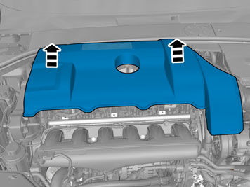
| | Applies to 6 cylinder engines Remove the engine cover by pulling it straight out up.
|
|  | | IMG-273586 |
|
| | |
|  | | IMG-273587 |
|
| | |
|  | | IMG-273588 |
|
| | |
| | | IMG-273585 |
|
| | Steps 46-48 apply to right-hand drive cars Applies to 6-cyl engines and diesel engines Remove the engine cover by pulling it straight out up.
|
|  | | IMG-273589 |
|
| | |
|  | | IMG-273590 |
|
| | Route the cable harness in-between the battery box and insulation for the cowl panel, and down to the rubber grommet. Secure using a cable ties on the outgoing cable harness from the battery box.
Note!
Make sure that the cable is positioned so that it is not damaged by heat or wear. |
Reinstall the headlamp.
|
| | |
|  | | IMG-235950 |
|
| | Applies to all models Cut off a small rubber nipple on the new rubber grommet. Lubricate the cable using soap solution and insert. Pull the cable into the passenger compartment. Adjust the length. Install the rubber grommet and move the heat shield on the cable towards the rubber grommet. Reinstall the engine splash guard and cover panel for the bumper. Lower the car. Reinstall the engine cover.
|
|  | | J3703487 |
|
| | Applies to left-hand drive cars Take the connector that was taped and connect it to the cable harness that was routed into the passenger compartment. Install the cable ends' pins in the connector, as illustrated:
Blue (BL) Green (GN) Violet (VO) Yellow (Y) White (W) Black (SB)
|
|  | | IMG-249180 |
|
| | Applies to right-hand drive cars Take the connector that was taped and connect it to the cable harness that was routed into the passenger compartment. Install the cable ends' pins in the connector, as illustrated:
Blue (BL) Black (SB) Violet (VO) White (W) Yellow (Y) Green (GN)
|
|  | | IMG-249181 |
|
| | |
|  | | IMG-249182 |
|
| | |
|  | | IMG-273591 |
|
| | |
|  | | IMG-273592 |
|
| | |
|  | | IMG-273593 |
|
| | |
|  | | IMG-242268 |
|
| | Reinstall: the glove box the sound barrier the sill trim panels the end face panel the rear seat cushion.
|