| | |
|  | | IMG-363036 |
|
| | Color symbols Note!
This colour chart displays (in colour print and electronic version) the importance of the different colours used in the images of the method steps. |
Used for focused part, the part that you are to do something with. Used as extra colors when you need to show or differentiate additional parts. Used for attachments that are to be removed/installed. May be screws, clips, connectors, etc. Used when the component is not fully removed from the vehicle but only hung to the side. Used for standard tools and special tools. Used as background color for vehicle components.
|
|  | | IMG-316263 |
|
| | |
|  | | IMG-331109 |
|
| | |
|  | | IMG-331110 |
|
| | |
|  | | IMG-342358 |
|
| | |
|  | | IMG-342359 |
|
| | |
|  | | IMG-342357 |
|
| | |
|  | | IMG-342360 |
|
| | |
|  | | IMG-378206 |
|
| | |
|  | | IMG-378210 |
|
| | |
|  | | IMG-378213 |
|
| | |
|  | | IMG-378214 |
|
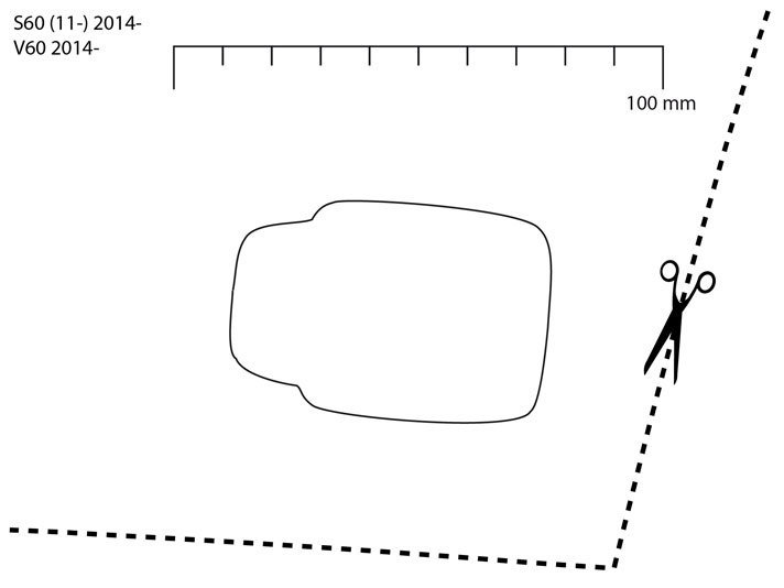
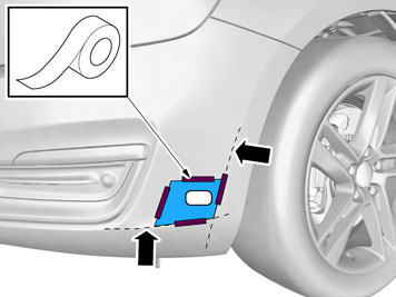
| | Accessory installation Note!
Cut carefully. It is easy to slip with the knife and move outside the template. |
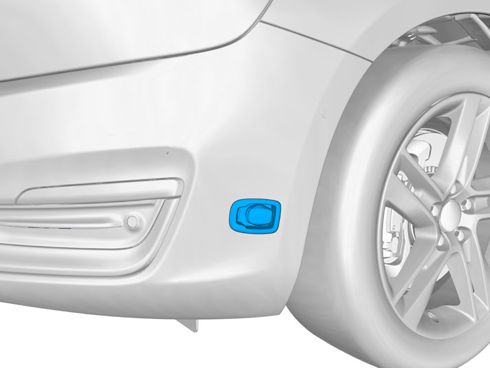
Remove the template and tape pieces. Install the protective cover for the front engine block heater socket from the kit. Check that it aligns. Adjust the hole using a knife or file as necessary. Smooth off the hole edges. Remove any swarf.
|
|  | | IMG-341071 |
|
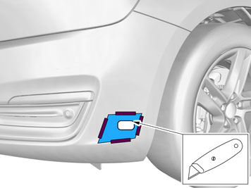
| | Press the protective cover (from the kit) into place in the hole cut in the bumper cover. Take the cable for the front engine block heater socket with ground lead from the kit and thread them through the protective cover.
|
|  | | IMG-342364 |
|
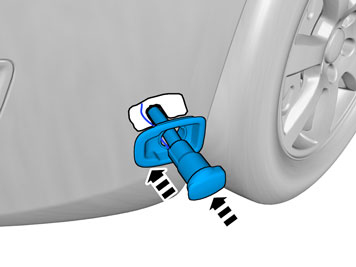
| | Install the attaching brace and nut from the kit. Plug the electrical connector into the front engine block heater socket. Use the connector as a counterhold when tightening. Tighten the front engine block heater socket to the bumper shell.
|
|  | | IMG-342365 |
|
| | |
|  | | IMG-340317 |
|
| | |
|  | | IMG-340576 |
|
| | |
|  | | IMG-341072 |
|
| | |
|  | | IMG-342366 |
|
| | |
|  | | IMG-231571 |
|
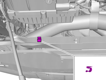
| | Drill a Ø4 mm (Ø5/32") hole for the front intake grounding on the underside of the left front side member as illustrated. Deburr the hole edges, remove the drill swarf and apply rustproofing agent. Take a screw and toothed washer from the kit. Tighten the ground cable.
|
|  | | IMG-279168 |
|
| | |
|  | | IMG-331126 |
|
| | |
|  | | IMG-331128 |
|
| | |
|  | | IMG-331133 |
|
| | |
|  | | IMG-331134 |
|
| | |
|  | | IMG-331135 |
|
| | Note!
This is an orientation image. |
|
|  | | IMG-331136 |
|
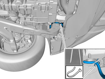
| | Cut the hose (1) as follows: Measure out for cutting the coolant hose between the oil cooler and the thermostat housing. Position the hose at the heater's lower connection, ensure that it runs around the oil filter properly and cut it.
|
|  | | IMG-331137 |
|
| | Smooth off the hose ends if necessary. Do not cut off too much of the hoses. Take hose clamps and tighten the hoses to the heater, preferably from underneath.
|
|  | | IMG-341074 |
|
| | |
|  | | IMG-214134 |
|
| | |
|  | | IMG-341073 |
|
| | |
|  | | D3601932 |
|
| | Note!
Do not get any grease on the surfaces of the connector. |
|
|  | | IMG-214136 |
|
| | Applies when only the engine block heater is installed If the passenger compartment connector socket is to be installed at the same time then install the junction connector now in accordance with illustration C and D, and connect the cables to it. |
|  | | IMG-344897 |
|
| | |
|  | | IMG-331148 |
|
| | Applies when fitting passenger compartment connector at the same time If the passenger compartment connector is to be installed at the same time, install the junction connector now. Lubricate the O-rings on the contacts as previously. Connect: cable (1) from the front intake cable (2) to the passenger compartment connector socket cable (3) to the heater
|
|  | | IMG-331153 |
|
| | |
| | | D3601932 |
|
| | Applies to all vehicles Note!
Do not get any grease on the surfaces of the connector. |
|
|  | | IMG-331158 |
|
| | |
|  | | IMG-331159 |
|
| | |
|  | | IMG-331160 |
|
| | |
|  | | IMG-342421 |
|
| | |
|  | | IMG-342422 |
|
| | |
|  | | IMG-342423 |
|
| | |
|  | | IMG-331163 |
|
| | |
|  | | IMG-317784 |
|
| | |
|  | | IMG-340577 |
|
| | |
|  | | IMG-340318 |
|
| | |