| | |
| | Read through all of the instructions before starting installation. Notifications and warning texts are for your safety and to minimise the risk of something breaking during installation. Ensure that all tools stated in the instructions are available before starting installation. Certain steps in the instructions are only presented in the form of images. Explanatory text is also given for more complicated steps. In the event of any problems with the instructions or the accessory, contact your local Volvo dealer.
|
| | |
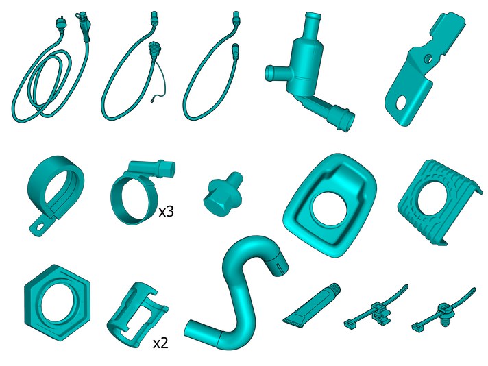
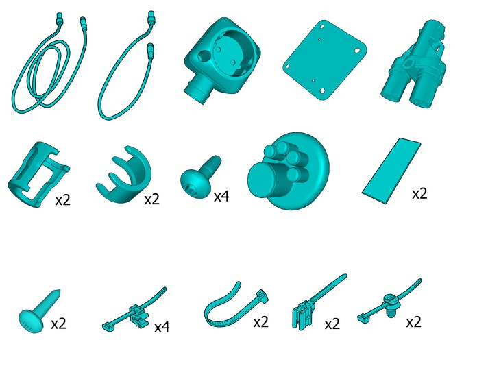
| | There may be parts in the accessories kit that are not needed for this installation. |
| | |
|  | | IMG-440436 |
|
| | Note!
This colour chart displays (in colour print and electronic version) the importance of the different colours used in the images of the method steps. |
Used for focused component, the component with which you will do something. Used as extra colors when you need to show or differentiate additional parts. Used for attachments that are to be removed/installed. May be screws, clips, connectors, etc. Used when the component is not fully removed from the vehicle but only hung to the side. Used for standard tools and special tools. Used as background color for vehicle components. Used for accessory components.
|
| | |
|  | | IMG-442590 |
|
| | |
|  | | IMG-431485 |
|
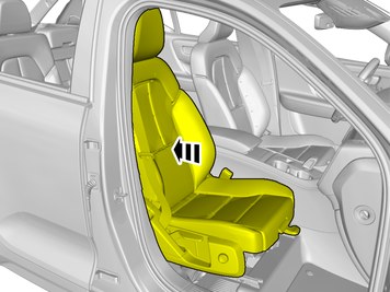
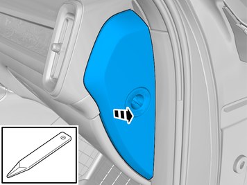
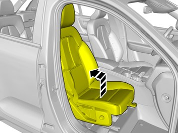
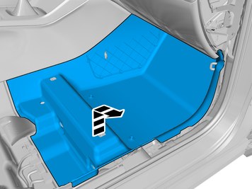
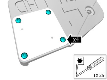
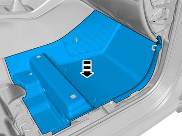
| | Remove the panel. Disconnect the connector, if applicable. |
|  | | IMG-431600 |
|
| | |
|  | | IMG-431605 |
|
| | |
|  | | IMG-443405 |
|
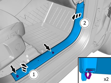
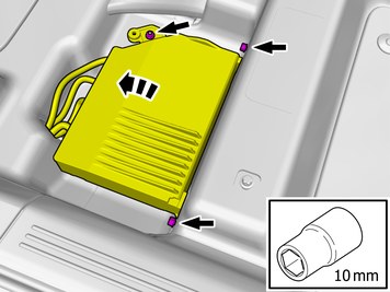
| | Remove the screws.
Tightening torque: Front seat to body
, 40 Nm
|
|  | | IMG-442591 |
|
| | |
|  | | IMG-443407 |
|
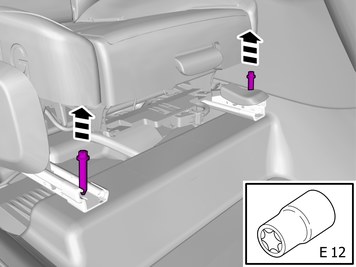
| | Remove the screws.
Tightening torque: Front seat to body
, 40 Nm
|
|  | | IMG-442592 |
|
| | |
|  | | IMG-445881 |
|
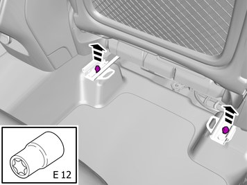
| | Remove the screws. Remove the nut. Fold marked part aside. |
|  | | IMG-431651 |
|
| | |
|  | | IMG-431640 |
|
| | |
|  | | IMG-431652 |
|
| | |
| | |
|  | | IMG-444102 |
|
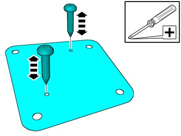
| | Screw and unscrew to ease assembly later. |
|  | | IMG-440386 |
|
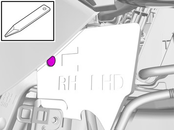
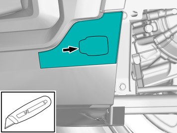
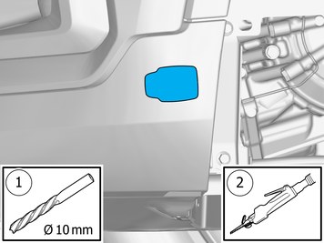
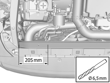
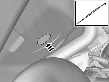
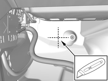
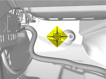
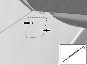
| | Place the component where indicated in the graphic. Make a hole, using the tool indicated. Use: Scribe
|
|  | | IMG-440394 |
|
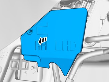
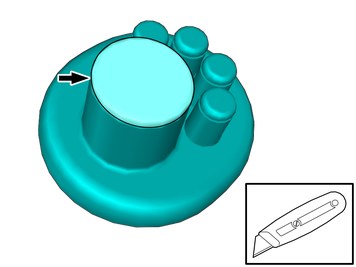
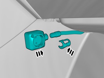
| | Install components that come with the accessory kit. |
|  | | IMG-440395 |
|
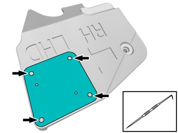
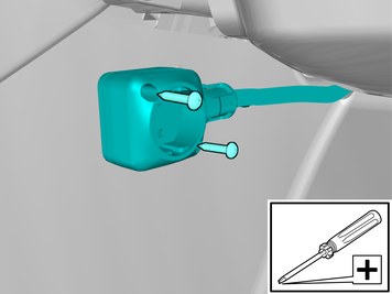
| | Install components that come with the accessory kit. Remove the protective film. |
|  | | IMG-440401 |
|
| | Note!
Press and apply pressure to the part over the tape for at least 20 seconds. |
Install the marked components. |
| | |
|  | | IMG-439740 |
|
| | |
|  | | IMG-400006 |
|
| | Drain the cooling system according to service information in VIDA: Information / Repair / Cleaning, Inspection and Adjustment / 2 Engine with mountings and equipment / 26 Cooling system / 261 radiator and connections / Cooling system – draining, charging and bleeding.
Use special tool: T9997669, Key
|
|  | | IMG-403425 |
|
| | Remove the marked detail/details. Use: Pliers 31423632
|
|  | | IMG-426018 |
|
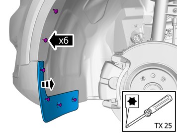
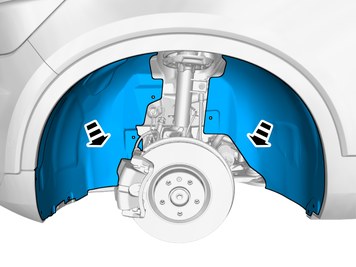
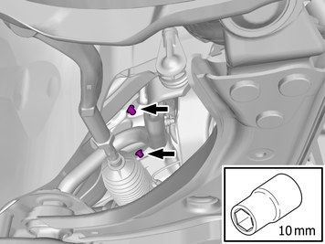
| | Remove the screws. Remove the marked part. |
| | Repeat the steps when removing on opposite side. |
|  | | IMG-438237 |
|
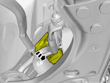
| | Remove the screws. Remove the marked part. |
|  | | IMG-439752 |
|
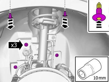
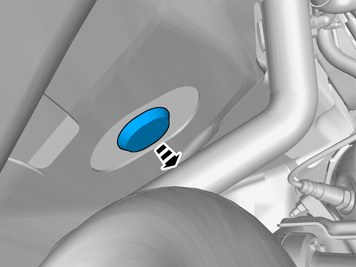
| | Remove the clips. Remove the nuts. |
|  | | IMG-439754 |
|
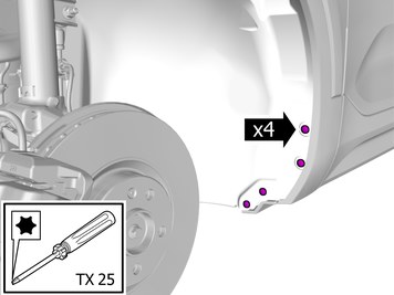
| | Remove the screws. Remove the clip. |
|  | | IMG-439755 |
|
| | |
| | |
|  | | IMG-439819 |
|
| | |
|  | | IMG-440215 |
|
| | Secure the template with tape. |
|  | | IMG-440216 |
|
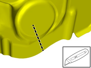
| | Caution!
Cut carefully to avoid unintentional damage or personal injury. |
Cut out following the template. Make a mark by cutting a thin cut. Remove template. |
|  | | IMG-440041 |
|
| | Use a drill with the stated size Use: Air-powered air saw
|
|  | | IMG-440192 |
|
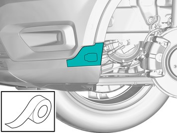
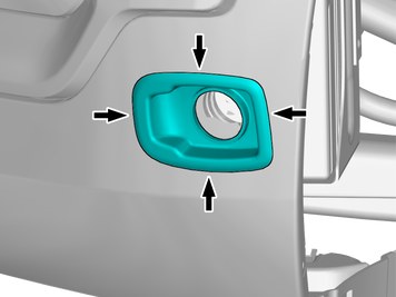
| | Install component that comes with the accessory kit. Check that the flange of the part is in full contact with bumper cover. Adjust the hole with a file or knife as necessary. |
|  | | IMG-440181 |
|
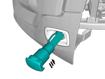
| | Install component that comes with the accessory kit. |
|  | | IMG-440194 |
|
| | |
|  | | IMG-440190 |
|
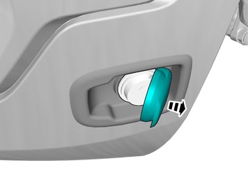
| | Note!
Do not fully tighten the nut yet. |
Install components that come with the accessory kit. |
|  | | IMG-440208 |
|
| | Install component that comes with the accessory kit. This is used as a counterhold. |
|  | | IMG-440209 |
|
| | Tighten the nut. Use hands only. |
|  | | IMG-440605 |
|
| | |
|  | | IMG-440607 |
|
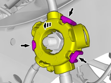
| | Release the catches. Fold marked part aside. |
|  | | IMG-440610 |
|
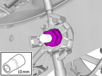
| | Remove the nut. The item is to be reused. |
|  | | IMG-440611 |
|
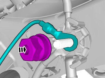
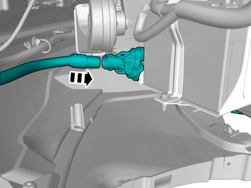
| | Connect the prerouted cable. Install the nut.
Tightening torque: M6
, 10 Nm
|
|  | | IMG-440608 |
|
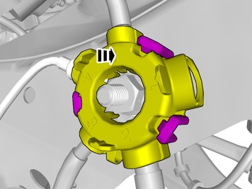
| | Reinstall the removed part. |
|  | | IMG-440316 |
|
| | Caution!
No grease on contact surfaces. |
|
|  | | IMG-440945 |
|
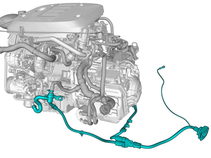
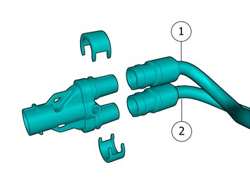
| | Use details according to image. Passenger Compartment Connector Cable Engine heater cable
|
|  | | IMG-440990 |
|
| | Passenger Compartment Connector Cable Engine heater cable
Assemble components that come with the accessory kit. |
|  | | IMG-440995 |
|
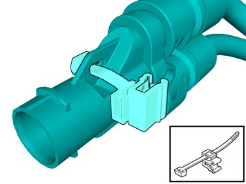
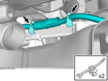
| | Place the cable tie as illustrated. |
|  | | IMG-442605 |
|
| | |
|  | | IMG-442606 |
|
| | |
|  | | IMG-441390 |
|
| | Caution!
No grease on contact surfaces. |
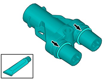
Lubricate the O-ring. |
|  | | IMG-442607 |
|
| | |
|  | | IMG-442608 |
|
| | |
|  | | IMG-442609 |
|
| | |
|  | | IMG-442610 |
|
| | Note!
Image shows vehicle without battery. |
Attach the clip. |
| | |
|  | | IMG-440016 |
|
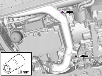
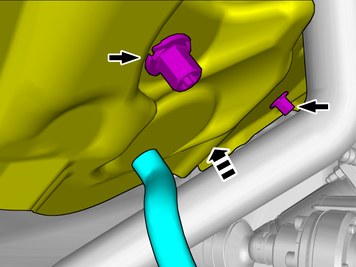
| | Remove the screws.
Tightening torque: M8
, 24 Nm
|
|  | | IMG-440017 |
|
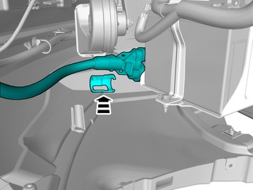
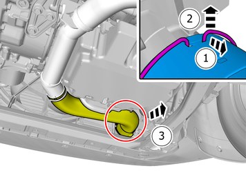
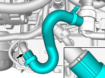
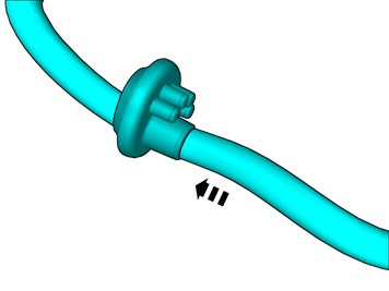
| | Release the lock. Undo the hose from the connection. |
|  | | IMG-440018 |
|
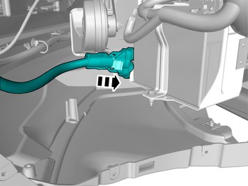
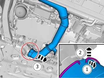
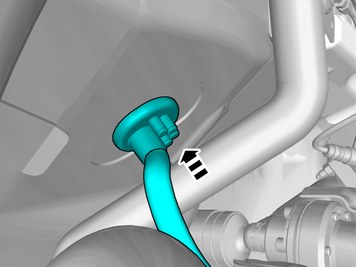
| | Release the lock. Remove the marked part. |
|  | | IMG-440019 |
|
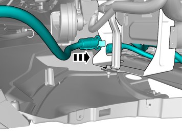
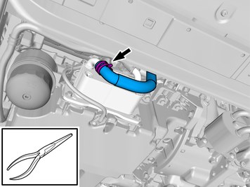
| | Warning!
Be prepared to collect escaping fluid. |
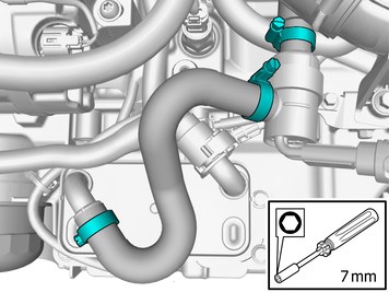
Loosen the hose clamp. Undo the hose from the connection. |
|  | | IMG-440255 |
|
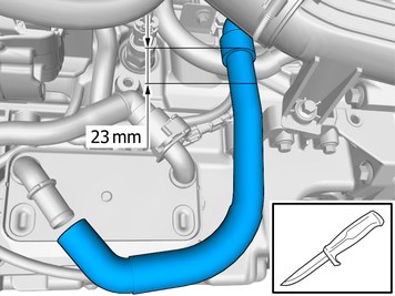
| | Caution!
Cut carefully to avoid unintentional damage or personal injury. |
|
| | |
|  | | IMG-440260 |
|
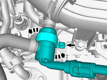
| | Note!
Do not fully tighten the bolt. |
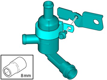
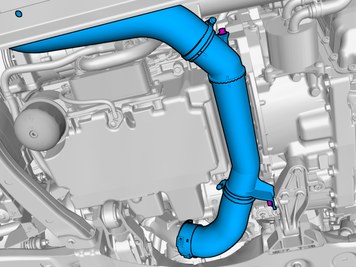
Assemble components that come with the accessory kit. |
|  | | IMG-452410 |
|
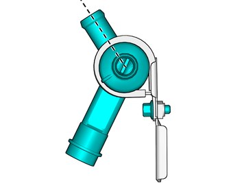
| | Adjust the position of the component according to image. Tighten the screw. |
|  | | IMG-440265 |
|
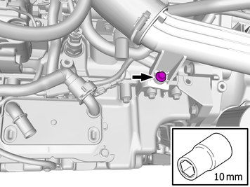
| | Remove the screw. The item is to be reused. |
|  | | IMG-440290 |
|
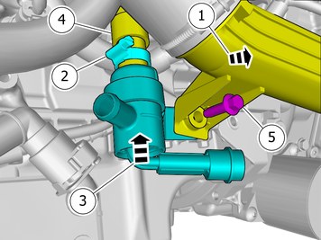
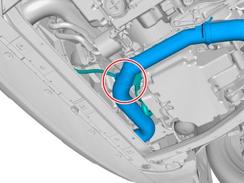
| | Fold marked part aside. Attach the hose clamp Install the marked components. Install the hose. Reinstall the screw.
|
|  | | IMG-440300 |
|
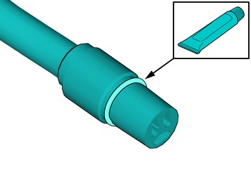
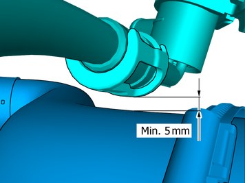
| | Note!
The markings must be opposite each other. |
Install components that come with the accessory kit. |
|  | | IMG-440309 |
|
| | |
| | | IMG-441390 |
|
| | Caution!
No grease on contact surfaces. |
Lubricate the O-ring. |
|  | | IMG-440323 |
|
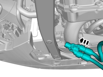
| | Connect the prerouted cable. Install the catch. |
|  | | IMG-448210 |
|
| | Passenger Compartment Connector Cable |
|  | | IMG-440440 |
|
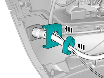
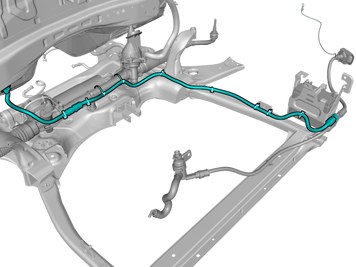
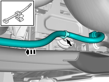
| | Place the cable tie as illustrated. Position/route the cable as illustrated. Tighten the cable tie. |
|  | | IMG-440442 |
|
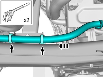
| | Place the cable tie as illustrated. Position/route the cable as illustrated. Tighten the cable ties. |
|  | | IMG-440444 |
|
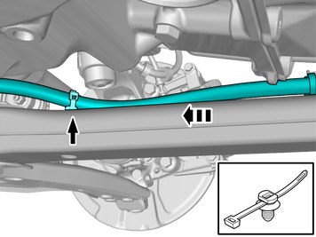
| | Place the cable tie as illustrated. Position/route the cable as illustrated. Tighten the cable tie. |
|  | | IMG-440464 |
|
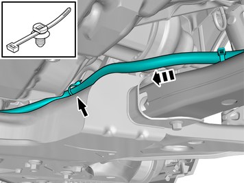
| | Place the cable tie as illustrated. Position/route the cable as illustrated. Tighten the cable tie. |
|  | | IMG-440530 |
|
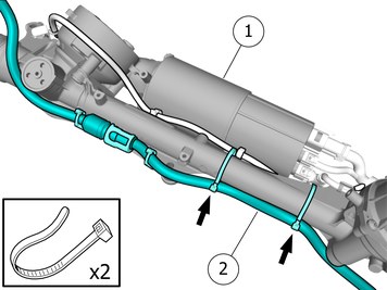
| | Steering gear Passenger Compartment Connector Cable
|
|  | | IMG-440820 |
|
| | Caution!
Install the cable tie only around steering gear and new wiring harness. The cable tie must not be installed around the existing wiring harness. |
Position/route the cable as illustrated. Install the cable. Use a cable tie |
| | | IMG-441390 |
|
| | Caution!
No grease on contact surfaces. |
Lubricate the O-ring. |
|  | | IMG-440901 |
|
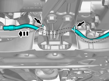
| | Use detail according to image. |
|  | | IMG-440822 |
|
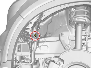
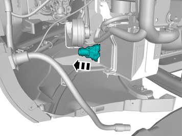
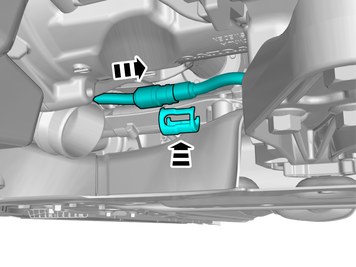
| | Connect the cable. Install the catch. |
|  | | IMG-440826 |
|
| | Place the cable tie as illustrated. Position/route the cable as illustrated. Tighten the cable ties. |
|  | | IMG-441020 |
|
| | Reinstall the removed part. |
|  | | IMG-441027 |
|
| | |
|  | | IMG-441032 |
|
| | Note!
If the result is not within the specified tolerances, follow the step below. |
|
|  | | IMG-441078 |
|
| | Loosen the screws. Pull the component in direction of the arrow. Tighten the screw. |
|  | | IMG-442615 |
|
| | |
|  | | IMG-442616 |
|
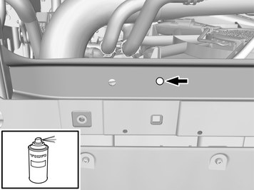
| | Use: , Rust inhibitor, low viscosity
|
|  | | IMG-442617 |
|
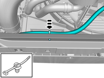
| | Place the cable tie as illustrated. Position/route the cable as illustrated. Tighten the cable tie. |
| | |
|  | | IMG-440935 |
|
| | |
|  | | IMG-440939 |
|
| | Fold the insulation aside. |
|  | | IMG-440940 |
|
| | Make a cut in the insulation. |
|  | | IMG-440955 |
|
| | Remove the marked part. The part is not to be reused. |
|  | | IMG-440965 |
|
| | Push the tool through the insulation into the compartment. Use: Scribe
Allow the tool to remain. |
|  | | IMG-441376 |
|
| | |
|  | | IMG-441380 |
|
| | Fold the insulation aside. Remove the tool. |
| | |
|  | | IMG-440946 |
|
| | |
|  | | IMG-441082 |
|
| | Pull the wiring through.
Use special tool: T9814204, Expander pliers
|
|  | | IMG-441083 |
|
| | Caution!
Make sure that the rubber grommet seals properly to the body. |
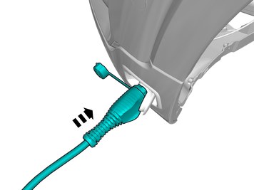
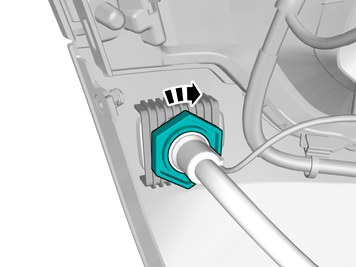
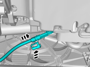
Insert the cable in to the passenger compartment, adjust the cable length out into the engine compartment and secure the rubber grommet. |
|  | | IMG-441089 |
|
| | Refit the insulation. Install the nuts |
|  | | IMG-442618 |
|
| | Install the marked component. |
|  | | IMG-442626 |
|
| | Take a scriber and make a hole in the carpet opposite the two holes in the bracket. |
| | | IMG-441390 |
|
| | Caution!
No grease on contact surfaces. |
Lubricate the O-ring. |
|  | | IMG-444091 |
|
| | Install components that come with the accessory kit. |
|  | | IMG-442627 |
|
| | |
| | |
| | | IMG-400006 |
|
| | Fill the cooling system according to the service information in VIDA: Information / Repair / Cleaning, Inspection and Adjustment / 2 Engine with mountings and equipment / 26 Cooling system / 261 radiator and connections / Cooling system – draining, charging and bleeding.
Use special tool: T9512955, Cover
Use special tool: T9814192, Hose
Use special tool: T9512957, Coolant Reservoir
|
|  | | IMG-377070 |
|
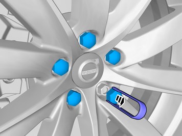
| | Reinstall the removed parts in reverse order. |
|  | | IMG-405228 |
|
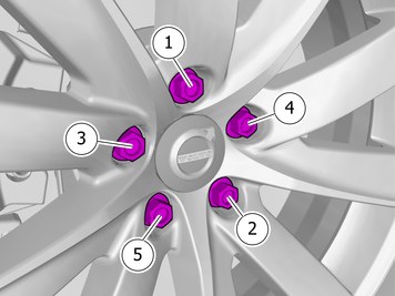
| | Note!
Make sure to follow the sequence indicated. |
Tightening torque: Aluminum wheel rim to wheel hub
Stage 1:
4 Nm
Stage 2:
50 Nm
Stage 3:
140 Nm
|