| | |
|  | | IMG-245980 |
|
| | Note!
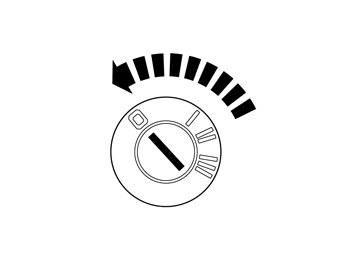
Wait at least three minutes before unplugging the connectors or removing other electrical equipment. |
|
|  | | R8503999 |
|
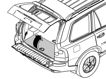
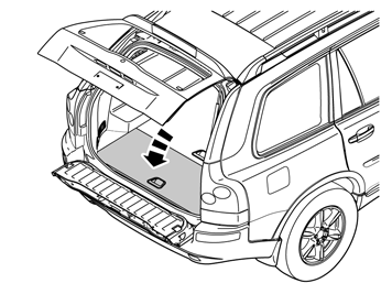
| | Applies to cars with two rows of seats Fold up the middle, rear floor hatch. Unhook the straps. Detach the storage box underneath and lift it out. Fold back the floor hatch. Pull the floor hatch backwards and lift it out.
Applies to cars with three rows of seats Applies to all models |
|  | | R3100131 |
|
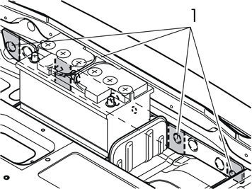
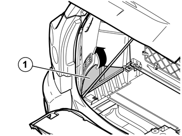
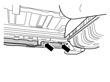
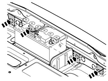
| | Remove the pre-punched pieces (1) from the insulation panel in the rear crossmember by cutting them off at the markings. Remove the four sleeve nuts holding the bumper in place. They are in the holes under the insulation panel. Lift them out and remove them using a magnet
|
|  | | IMG-246058 |
|
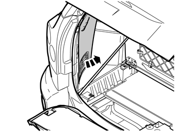
| | Applies to cars with rear parking assistance |
|  | | IMG-246059 |
|
| | |
|  | | IMG-310703 |
|
|  | | IMG-310704 |
|
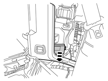
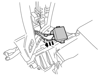
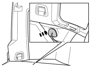
| | A and B Detach the control module, it is secured by Velcro. Remove the connector for the cable to the sensors.
|
|  | | IMG-310705 |
|
| | |
|  | | IMG-310706 |
|
| | |
|  | | IMG-310707 |
|
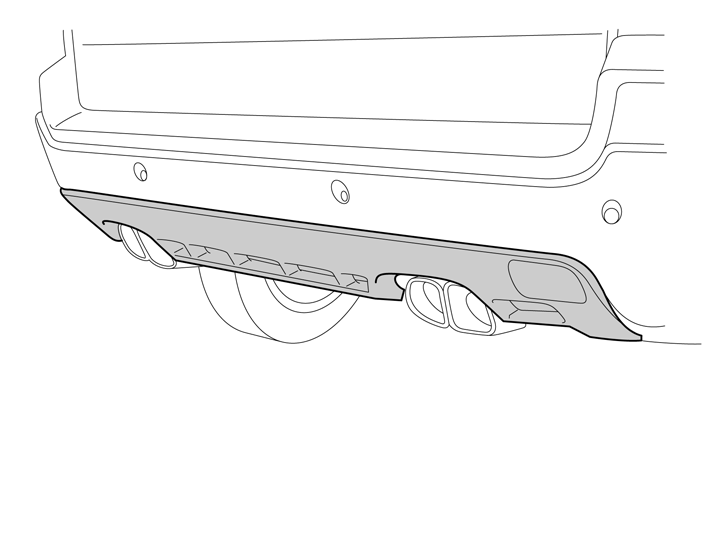
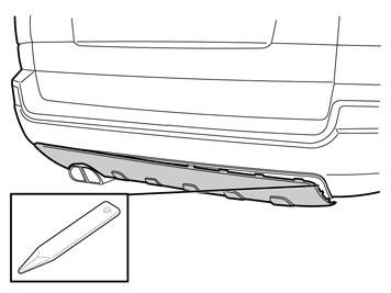
| | Carefully pry the lower panel away from the bumper cover using a weatherstrip tool. Start at the lowermost edge. The skid plate is secured by surrounding catches. Place to one side. A new panel is in the kit.
|
|  | | IMG-246027 |
|
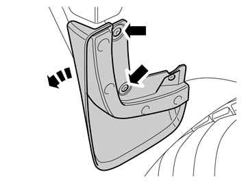
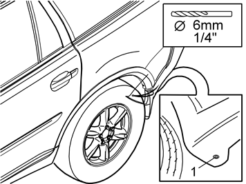
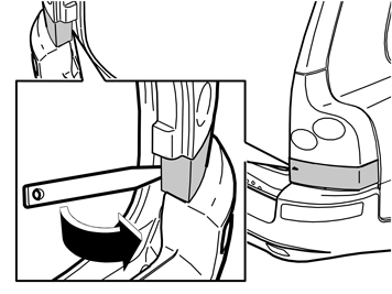
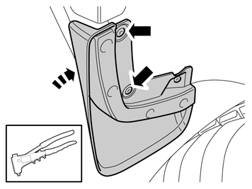
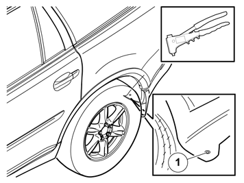
| | Applies to cars with mudguards Drill out the two rivets using a 6 mm (1/4") drill bit. Leave the inner rivet in place. Turn the mud guard outwards/downwards. Repeat the operation on the other side.
|
|  | | IMG-311486 |
|
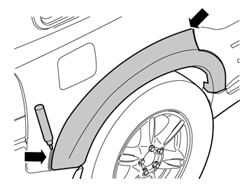
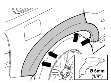
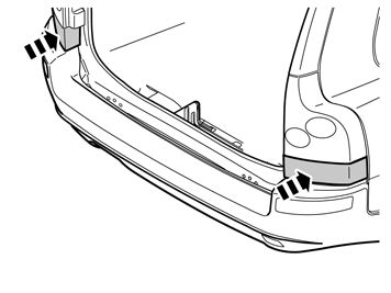
| | Applies to cars with body kit Steps 11-17 are carried out on both sides Note!
Wash and, if necessary, degrease the bumper and rear wings before removing the decor panels. |
|
|  | | IMG-310885 |
|
| | |
|  | | IMG-310884 |
|
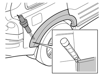
| | Caution!
Do not damage painted surfaces. |
Hint
If the tape is securely attached, carefully heat the tape using a hot air gun to soften it up. |
|
|  | | IMG-310883 |
|
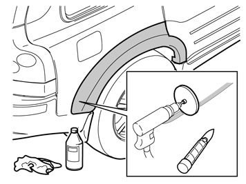
| | Caution!
Do not use the tool on painted surfaces that have plastic carriers. On painted surfaces with plastic carriers the adhesive residue must be removed mechanically. Use a plastic weatherstrip and then clean using isopropanol. |
|
|  | | IMG-310905 |
|
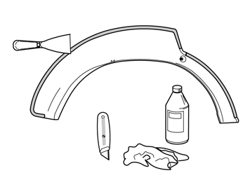
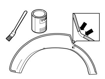
| | Preparing decor panel rear wing |
|  | | IMG-311504 |
|
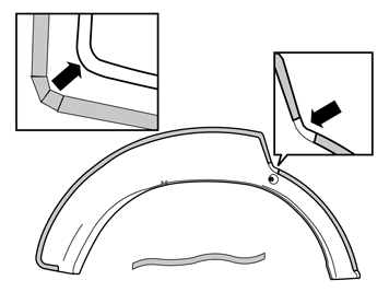
| | Caution!
Apply the tape after, the earliest 15 minutes, and at the latest 3 hours after applying the primer. |
|
|  | | IMG-310963 |
|
| | Installing the decor panel rear wing, as in last step. For installation of decor panel rear wing, see: VIDA Installation instructions, accessories 86, bumper, mudguards 863 protectors and rubber protection Body kit Fastening side panel, rear fender
|
|  | | R8600883 |
|
| | |
|  | | R8600873 |
|
| | |
|  | | IMG-246025 |
|
| | |
|  | | IMG-246028 |
|
|  | | IMG-246123 |
|
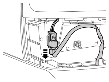
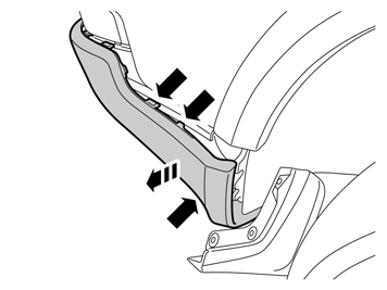
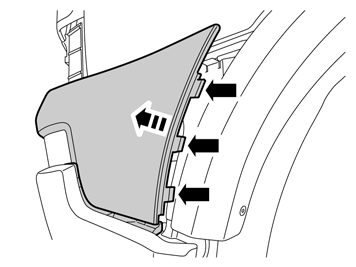
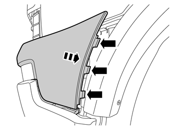
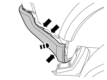
| | A and B Pull off the lower section of the bumper cover at the front edge so that the two hooks at the upper edge, and the hooks on the inside, release. Grasp the lower edge of the upper section of the bumper cover. Pull straight out so that the three hooks release. The hooks may be hard to release, if so, release using a weatherstrip tool. Pull out the ends further until the four hooks, which are horizontally positioned at the upper edge, release. Repeat the operation on the other side.
|
|  | | IMG-246029 |
|
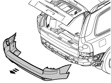
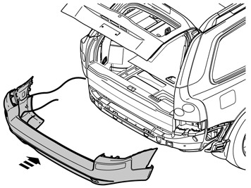
| | Fold up the lower tailgate. Pull the bumper backwards and remove. Place the bumper on a suitable surface that will not damage the paint. Remove the remaining parts of the removed rivets.
|
|  | | IMG-310983 |
|
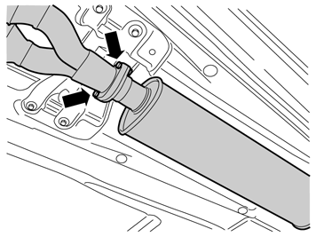
| | Applies to cars with 8-cylinder engine Note!
New clamp nuts and gasket must be used when installing the new exhaust system. |
|
|  | | IMG-310984 |
|
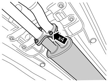
| | Applies to cars with 6-cylinder engine Note!
New clamp nuts and gasket must be used when installing the new exhaust system. |
|
|  | | IMG-311023 |
|
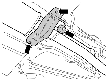
| | Applies to cars with 8-cylinder and 6-cylinder engines Remove the screws in the bracket under the exhaust pipe. Remove the bracket with rubber mountings from the exhaust pipe. Use low temperature grease to get the rubber mountings to slide off the mounting hook more easily.
|
|  | | IMG-311043 |
|
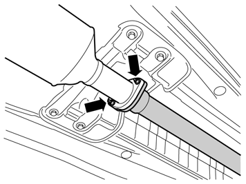
| | Applies to cars with 5-cylinder diesel engine Note!
New clamp nuts and gasket must be used when installing the new exhaust system. |
|
|  | | IMG-311063 |
|
| | |
|  | | IMG-311064 |
|
| | |
|  | | IMG-311066 |
|
| | Applies to cars without a tow hitch Note!
Two mechanics are needed for this step. |
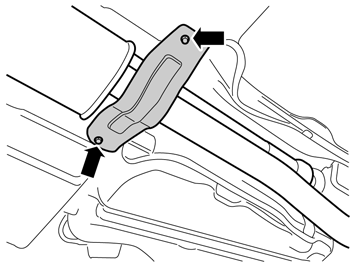
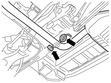
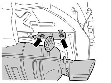
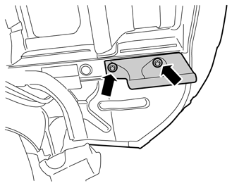
Remove the screws in the bracket underneath the left side member. Pull out the exhaust pipe at the front joint and place to one side. The rubber mounting with bracket will not be reused. New ones are in the kits. The screws will be reused. Place the exhaust system to one side. New system in the kit. Remove the gasket at the front joint and discard it. New nuts and new gasket will be used at installation.
|
|  | | IMG-311067 |
|
| | |
| 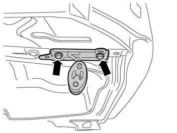 | | IMG-311323 |
|
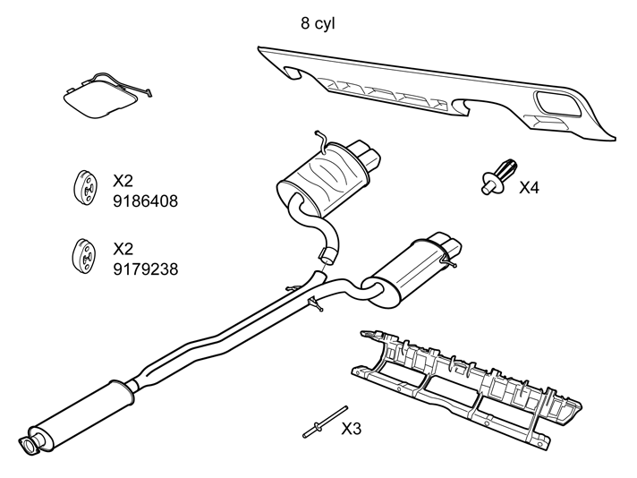
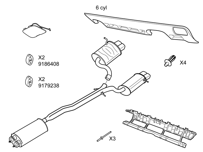
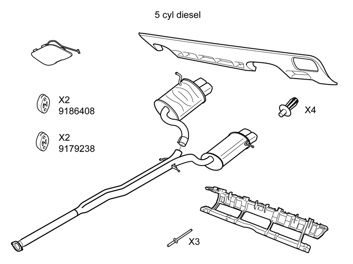
| | Take the left-hand mounting bracket from mounting kit exhaust system for cars without tow hitch and rubber mounting part no. 9186408 from installation kit exhaust system 8, 6 or 5 cyl diesel and install the rubber mounting on it. Install the unit under the side member and install existing screws. Do not tighten hard yet.
|
| 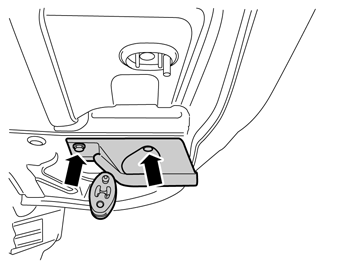 | | IMG-311324 |
|
| | Take the new towing eyelet from installation kit exhaust system for cars without tow hitch and rubber mountingpart no. 9186408 frominstallation kit exhaust system 8, 6 or 5 cyl diesel and install the rubber mounting again on it. Install the unit under the side member and install existing screws. Do not tighten hard yet.
|
| 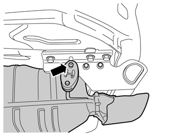 | | IMG-311403 |
|
| | Applies to cars with a tow hitch Note!
Two mechanics are needed for this step. |
Unhook the silencer's rubber mounting from the hook on the tow bar's side panel. Pull out the exhaust pipe at the front joint and place to one side. The rubber mounting will not be reused. New mounting in the kit. Place the exhaust system to one side. New system in the kit. Remove the gasket at the front joint and discard it. New nuts and gasket will be used.
|
| 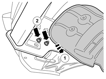 | | IMG-311423 |
|
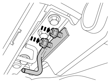
| | Fold the silencer heat shield to one side to access the lower nuts for the tow bar's reinforcement plate. Remove the nuts and discard them. Turn the screws and reinstall. Repeat the operation on the other side.
|
|  | | IMG-302184 |
|
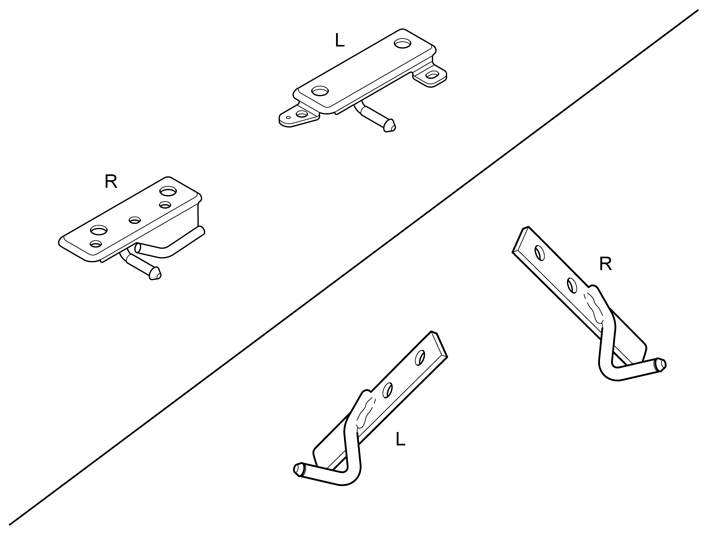
| | Take the mounting hooks from the kitTowbar, installation kit, XC90 R-design and install the hook on the screws. Take new nuts, install them and tighten to 50 Nm (37 lbf.ft.). Repeat the operation on the other side.
|
|  | | IMG-311424 |
|
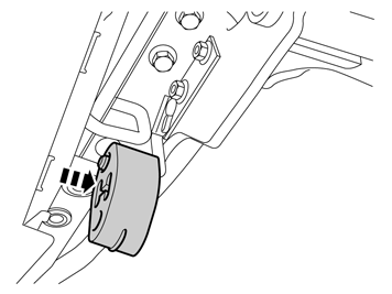
| | Install new rubber mounting part no. 9186408 from installation kit exhaust system 8, 6 or 5 cyl diesel on the hook. Repeat the operation on the other side.
|
|  | | IMG-311425 |
|
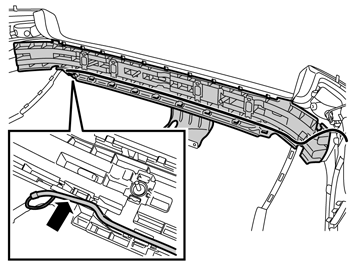
| | Applies to cars with parking assistance |
|  | | IMG-311505 |
|
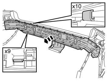
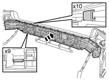
| | Applies to all models Unhook the ten catches at the upper edge of the bumper. Release the nine hooks in the middle of the bumper, at the same time as separating the rear section and outer section of the bumper. Remove the rear section from the bumper cover.
|
|  | | IMG-311444 |
|
|  | | IMG-311445 |
|
|  | | IMG-311446 |
|
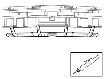
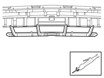
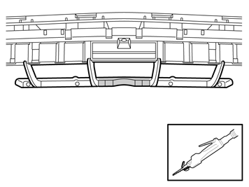
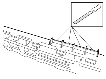
| | Applies to cars with a tow hitch A Detachable towbar B Fixed towbar C Hitch towbar
|
|  | | IMG-315623 |
|
| | |
|  | | IMG-315624 |
|
| | |
|  | | IMG-315625 |
|
| | |
|  | | IMG-315626 |
|
|  | | IMG-315627 |
|
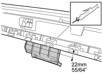
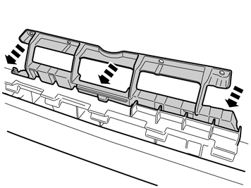
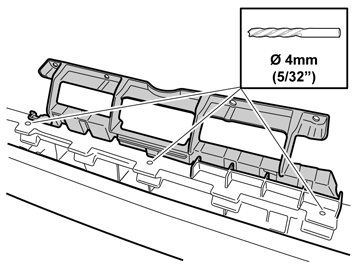
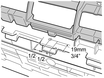
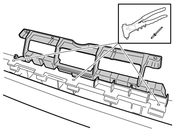
| | A Take measurements for the drilling of the three holes for the attachment of the holder. Secure the holder to the rear section properly and drill out the three holes through the rear section and holder. Remove any swarf.
B |
|  | | IMG-315628 |
|
| | |
|  | | IMG-311506 |
|
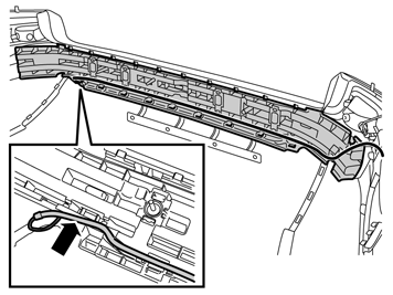
| | Applies to cars with parking assistance |
|  | | IMG-311450 |
|
| | Applies to cars with parking assistance |
|  | | IMG-311463 |
|
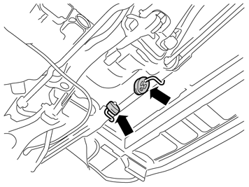
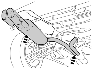
| | Applies to all models Take the two rubber mountings part no. 9179238 from kit exhaust system 8 or 6 cyl, or part no. 9492157 from exhaust system 5 cyl diesel. Install them in the suspension hooks in the bodywork.
|
|  | | IMG-311483 |
|
| | Note!
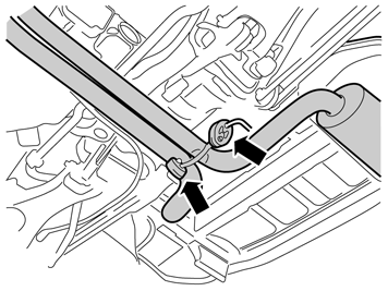
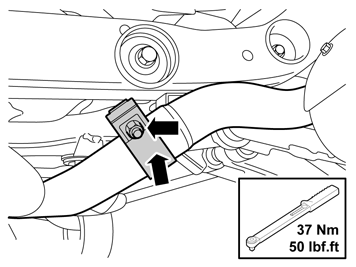
Two mechanics are needed for this step. Ensure that the mating surfaces in the joint between the various parts in the exhaust system are clean. All clamp nuts and gaskets must be replaced with new ones. |
|
|  | | IMG-311484 |
|
| | |
|  | | IMG-310983 |
|
| | Applies to cars with 8-cylinder engine |
|  | | IMG-310984 |
|
| | Applies to cars with 6-cylinder engine |
|  | | IMG-311023 |
|
| | Applies to cars with 6 and 8 cylinder engines |
|  | | IMG-311043 |
|
| | Applies to cars with 5-cylinder diesel engine |
|  | | IMG-311063 |
|
| | |
|  | | IMG-311524 |
|
| | |
|  | | IMG-311525 |
|
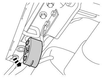
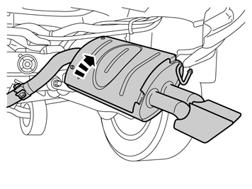
| | Take the remaining silencer from the kit and install it on the previously installed exhaust system. Hook the previously installed rubber mounting onto the silencer's hook. Do not tighten the joint in the silencer yet.
|
|  | | IMG-311545 |
|
|  | | IMG-311547 |
|
|  | | IMG-311548 |
|
| | A, B, and C Applies to cars with parking assistance |
|  | | IMG-311550 |
|
| | Applies to cars with mudguards |
|  | | IMG-311551 |
|
| | |
|  | | IMG-311552 |
|
| | |
|  | | IMG-311553 |
|
| | |
|  | | R3904120 |
|
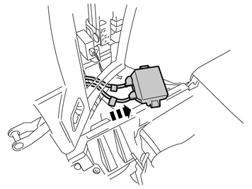
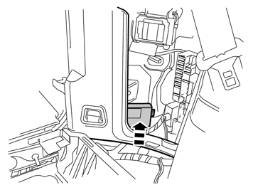
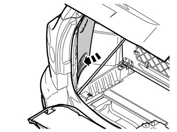
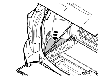
| | Applies to cars with parking assistance |
|  | | IMG-311554 |
|
|  | | IMG-311555 |
|
| | |
|  | | IMG-311567 |
|
| | |
|  | | IMG-311556 |
|
| | |
|  | | IMG-311557 |
|
| | |
|  | | IMG-302343 |
|
|  | | IMG-302344 |
|
|  | | IMG-302243 |
|
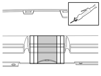
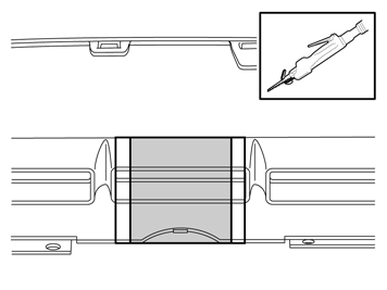
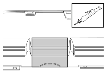
| | Applies to cars with a tow hitch Note!
Do not damage the paintwork of the bumper cover. |
A Detachable towbar B Fixed towbar C Hitch towbar
|
|  | | IMG-302283 |
|
|  | | IMG-311563 |
|
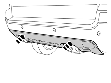
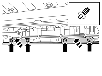
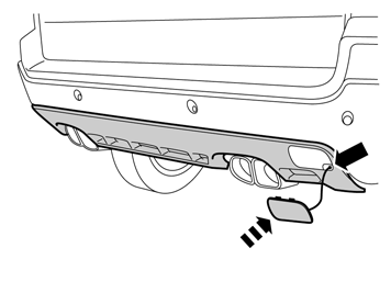
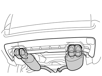
| | Applies to all models A and B |
|  | | IMG-311564 |
|
| | |
|  | | IMG-311565 |
|
|  | | IMG-311566 |
|
| | A Applies to cars without a tow hitch B |

