| | |
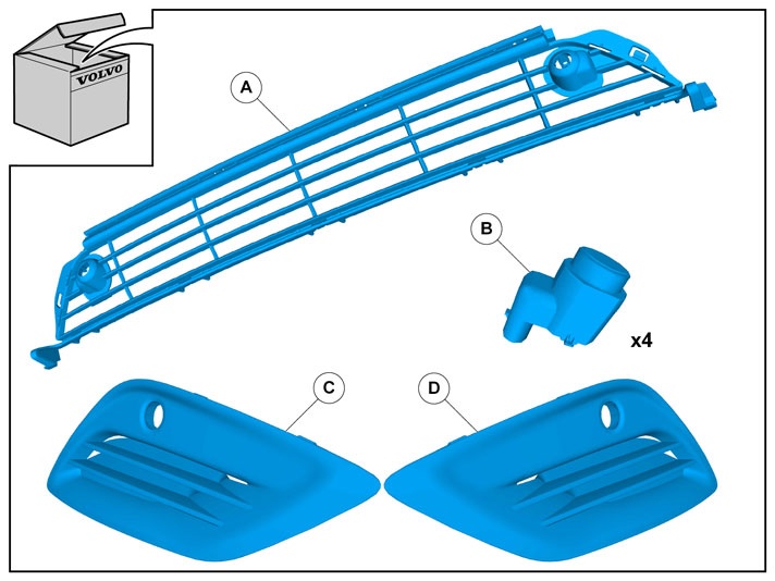
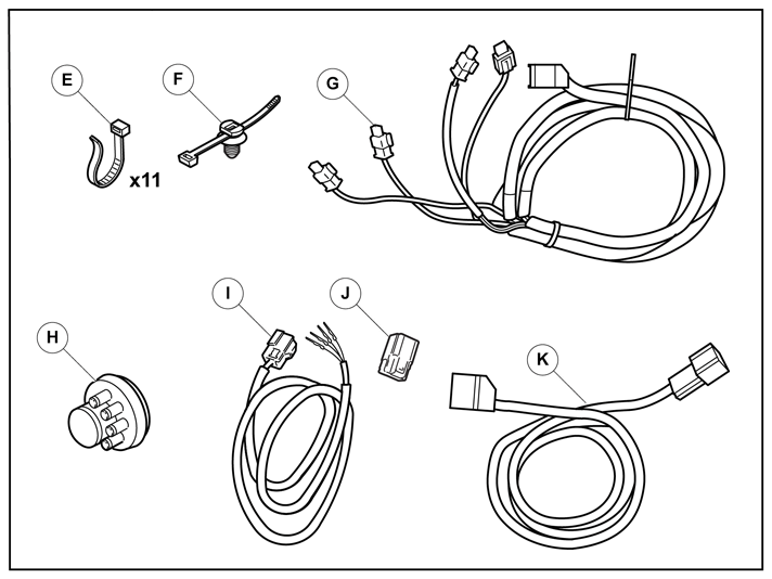
| | Read through all of the instructions before starting installation. Notifications and warning texts are for your safety and to minimise the risk of something breaking during installation. Ensure that all tools stated in the instructions are available before starting installation. Certain steps in the instructions are only presented in the form of images. Explanatory text is also given for more complicated steps. In the event of any problems with the instructions or the accessory, contact your local Volvo dealer.
|
| | |
| | These installation instructions show installation on left hand drive cars. When installing on right-hand drive cars, perform the procedures on the opposite side and/or mirrored. Where the procedure differs, the right-hand version is also shown with text and image. |
|  | | IMG-332193 |
|
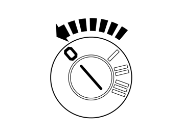
| | Set the ignition key to position 0. |
|  | | IMG-340600 |
|
| | |
|  | | IMG-308353 |
|
| | |
|  | | IMG-344927 |
|
| | |
|  | | IMG-344928 |
|
| | |
|  | | IMG-344929 |
|
| | |
|  | | IMG-344930 |
|
| | |
|  | | IMG-344451 |
|
| | |
|  | | IMG-269484 |
|
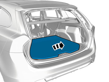
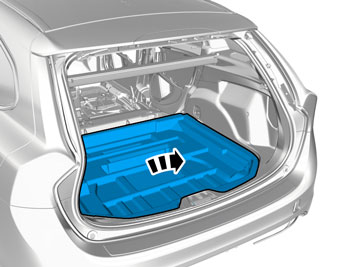
| | Fold the carpet to the side. |
|  | | IMG-307603 |
|
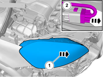
| | Locate the rubber grommet under the insulation and press it out. Facilitate cable routing by temporarily raising the floor bracket using a socket or similar. |
|  | | IMG-341901 |
|
| | |
|  | | IMG-341902 |
|
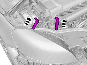
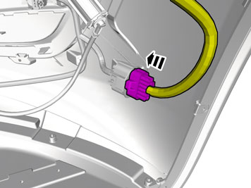
| | Disconnect the connector. On both sides. |
| | |
|  | | IMG-341903 |
|
| | |
|  | | IMG-341905 |
|
| | |
|  | | IMG-341906 |
|
| | |
|  | | IMG-307605 |
|
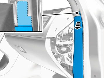
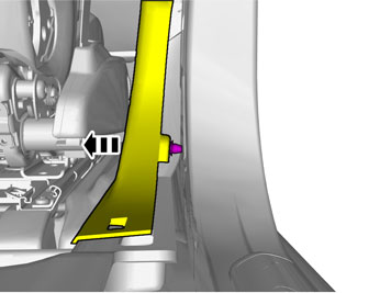
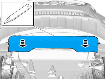
| | Remove the weatherstrips. |
|  | | IMG-307606 |
|
| | |
|  | | IMG-307607 |
|
| | |
|  | | IMG-343412 |
|
| | |
|  | | IMG-343413 |
|
| | |
|  | | IMG-341912 |
|
| | |
|  | | IMG-341913 |
|
| | |
| | Vehicles with headlamp washers |
|  | | IMG-341914 |
|
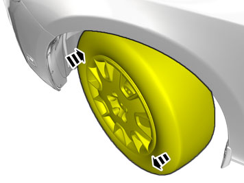
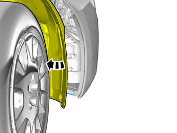
| | Fold the wing liner to one side. |
|  | | IMG-341915 |
|
| |
Note!
Tape the hose high up on the washer fluid reservoir to prevent washer fluid from coming out. |
Take a piece of washer hose. Tie a knot in it and place it on the washer pump to prevent the washer fluid reservoir from emptying.
|
| | |
|  | | IMG-341916 |
|
| | |
|  | | IMG-341917 |
|
| | |
|  | | IMG-341918 |
|
| | Fold the wing liner to one side. |
|  | | IMG-341923 |
|
| | |
|  | | IMG-307686 |
|
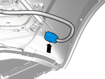
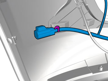
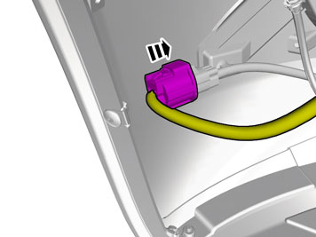
| | Disconnect the connector. |
|  | | IMG-307687 |
|
| | RHD: The procedure is carried out on the opposite side. |
|  | | IMG-307688 |
|
| | RHD: The procedure is carried out on the opposite side. |
|  | | IMG-341924 |
|
| | |
|  | | IMG-341927 |
|
| | |
|  | | IMG-341931 |
|
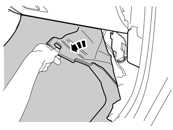
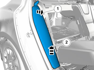
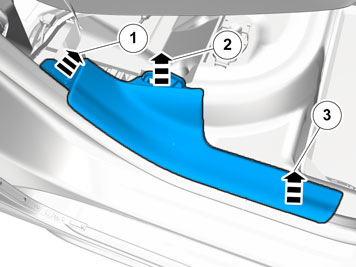
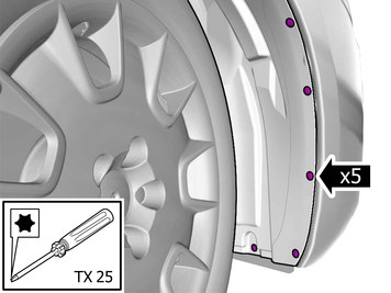
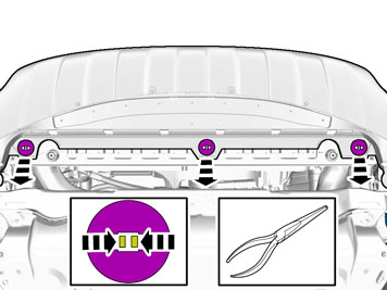
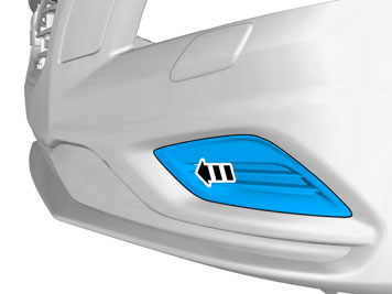
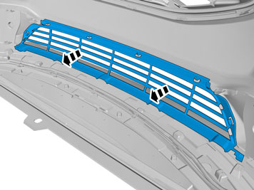
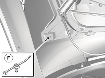
| | Remove the clips. Remove the screws. |
|  | | IMG-341932 |
|
| | |
|  | | IMG-341933 |
|
| | |
|  | | IMG-349911 |
|
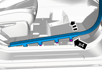
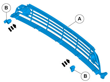
| | Repeat on the other side. |
|  | | IMG-349912 |
|
| | |
|  | | IMG-349914 |
|
| | Repeat on the other side. |
|  | | IMG-349913 |
|
| | |
|  | | IMG-349915 |
|
| | |
|  | | IMG-349916 |
|
| | |
|  | | IMG-349918 |
|
| | |
|  | | IMG-349919 |
|
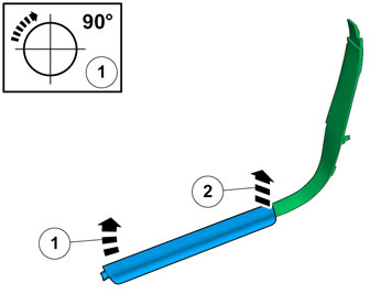
| | Repeat on the other side. |
|  | | IMG-341944 |
|
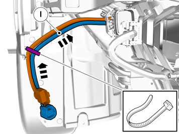
| | RHD: The cable harness is positioned mirrored. |
|  | | IMG-341945 |
|
| | |
|  | | IMG-341947 |
|
| | |
|  | | IMG-343387 |
|
| | |
| | |
|  | | IMG-341948 |
|
| | |
| | Right-hand drive vehicles |
|  | | IMG-343388 |
|
| | |
|  | | IMG-341950 |
|
| | |
| | |
|  | | IMG-341961 |
|
| | |
|  | | IMG-307882 |
|
| | |
| | Right-hand drive vehicles |
|  | | IMG-341962 |
|
| | |
|  | | IMG-341963 |
|
| | |
| | |
|  | | IMG-349920 |
|
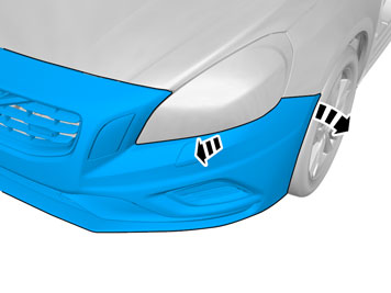
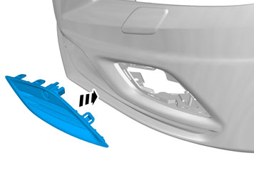
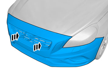
| | Place the Bumper Cover in position for installation. |
| | |
|  | | IMG-341965 |
|
| | |
| | Right-hand drive vehicles |
|  | | IMG-341966 |
|
| | |
|  | | IMG-341967 |
|
| | |
| | Vehicles with headlamp washers |
|  | | IMG-350323 |
|
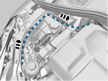
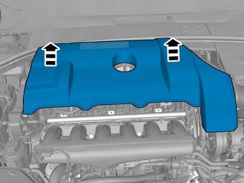
| | Reinstall the removed parts in reverse order. |
| | |
| | |
| | |
|  | | IMG-307909 |
|
| | Caution!
Make sure to locate the wiring in such a way that any damage caused by heat or excessive wear is avoided. |
Route the cable harness to the existing cable harness. Reinstall the headlamp. |
|  | | IMG-273585 |
|
| | |
|  | | IMG-273586 |
|
| | |
|  | | IMG-349742 |
|
| | |
|  | | IMG-273588 |
|
| | |
| | Right-hand drive vehicles |
| | | IMG-273585 |
|
| | |
|  | | IMG-307910 |
|
| | |
|  | | IMG-307911 |
|
| | |
|  | | IMG-307912 |
|
| | Caution!
Make sure to locate the wiring in such a way that any damage caused by heat or excessive wear is avoided. |
|
|  | | IMG-307913 |
|
| | |
|  | | IMG-307914 |
|
| | |
| | |
|  | | IMG-341971 |
|
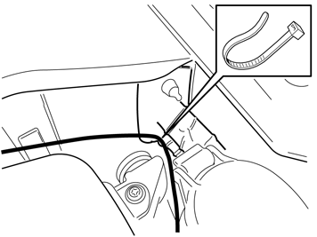
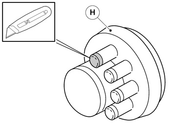
| | Note!
On some markets the rubber grommet may be covered by the heat shield. |
|
|  | | IMG-341973 |
|
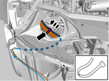
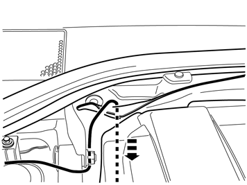
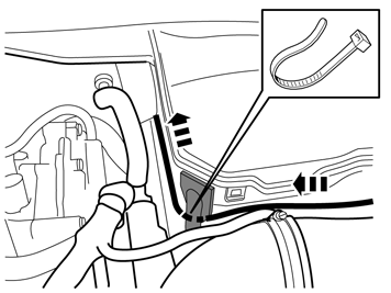
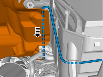
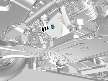
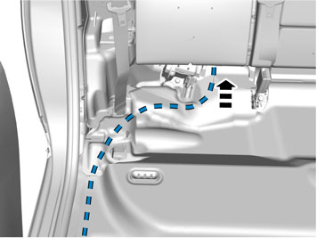
| | Pull the wiring through. Insert the cable in to the passenger compartment, adjust the cable length out into the engine compartment and secure the rubber grommet. |
| | |
|  | | IMG-349927 |
|
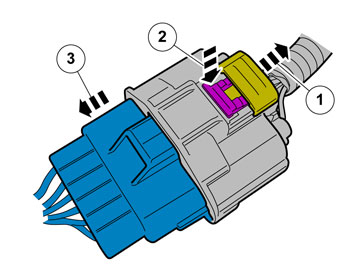
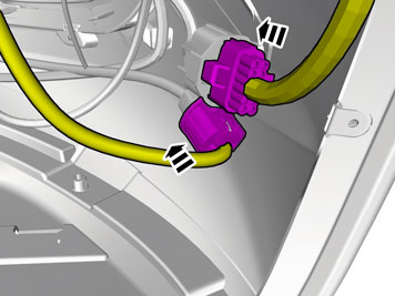
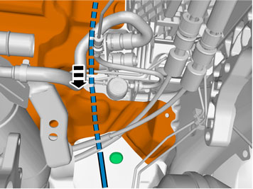
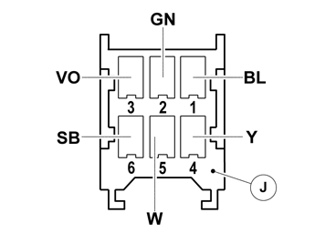
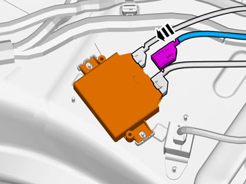
| | Release the connector's secondary lock. Connect the pre-routed cables to the 6-pin connector. Depress the secondary lock. |
| | Right-hand drive vehicles |
|  | | IMG-349926 |
|
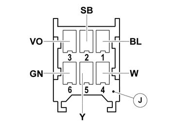
| | Release the connector's secondary lock. Connect the pre-routed cables to the 6-pin connector. Depress the secondary lock. |
| | |
|  | | IMG-349928 |
|
| | |
|  | | IMG-249181 |
|
| | |
|  | | IMG-349929 |
|
| | |
| | Right-hand drive vehicles |
|  | | IMG-308083 |
|
| | |
| | |
|  | | IMG-308084 |
|
| | |
|  | | IMG-346331 |
|
| | |
|  | | IMG-346347 |
|
| | |
|  | | IMG-346348 |
|
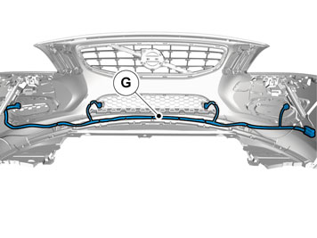
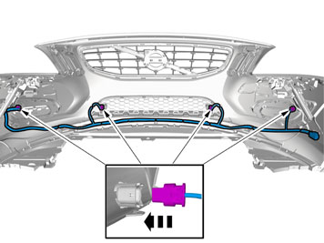
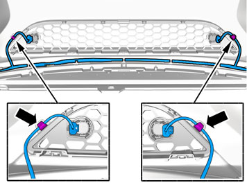
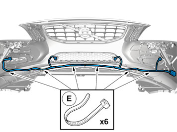
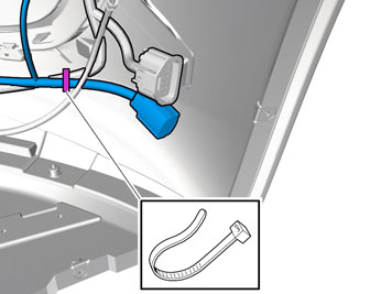
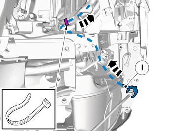
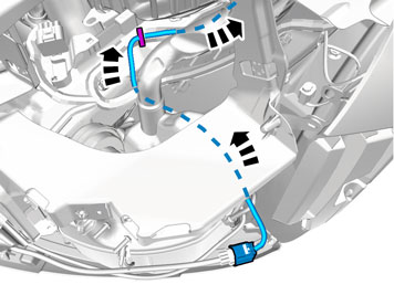
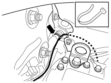
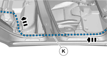
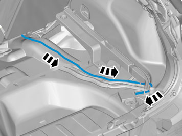
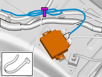
| | Note!
Extra cable length must be secured using cable ties. |
|
|  | | IMG-242268 |
|
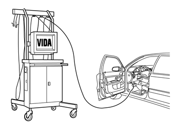
| | Download software (application) for the accessory's function according to the service information in VIDA. See VIDA or the accessories catalogue for software part number. |