| | |
|  | | IMG-246024 |
|
| | Note!
Wait at least three minutes before unplugging the connectors or removing other electrical equipment. |
|
| | |
|  | | IMG-240958 |
|
| | |
|  | | IMG-240957 |
|
| | |
|  | | IMG-241183 |
|
| | |
|  | | IMG-305743 |
|
| | |
|  | | IMG-241185 |
|
| | |
|  | | IMG-250926 |
|
| | Fold the central arm rest forward. Remove the central arm rest by grasping each end and pulling upwards until it releases at the rear edge from the backrest's lugs (1). Then pull it forwards until the holders (2) on the sides of the backrest have slid out of the corresponding cut-out (3) in the central arm rest.
|
|  | | IMG-250927 |
|
| | |
|  | | IMG-250928 |
|
| | |
|  | | IMG-250929 |
|
| | Note!
The backrest may be securely attached. |
|
|  | | IMG-250930 |
|
| | |
|  | | IMG-251368 |
|
| | |
|  | | IMG-277604 |
|
| | Remove the clips at the rear edge on the right rear side panel. Carefully pull the side panel off, starting at the front edge/upper edge and then straight back until all clips at the top edge have released. Fold the panel inwards. Release it from the anchorage eyelets and lift it out of the load floor support. Repeat steps 3 - 9 for the other side.
|
|  | | IMG-241200 |
|
| | |
|  | | IMG-321163 |
|
| | |
|  | | IMG-321183 |
|
| | |
|  | | IMG-321184 |
|
| | |
|  | | IMG-321185 |
|
| | |
|  | | IMG-321186 |
|
| | |
|  | | IMG-321187 |
|
| | |
|  | | IMG-257987 |
|
| | |
|  | | IMG-321188 |
|
| | |
|  | | IMG-321189 |
|
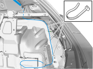
| | Note!
Make sure that it is routed so that there is no risk of chafing. |
|
|  | | IMG-321363 |
|
|  | | IMG-258619 |
|
| | Illustration A Illustration B Disconnect the large connector (1) from the accessory electronic module (AEM). First press in the catch (A). Pull the black locking handle (B) in the direction of the arrow until a click is heard. Disconnect the connector from the accessory electronic module (AEM). Disconnect the connector (2) from the accessory electronic module (AEM).
|
|  | | M3702530 |
|
| | Remove: the black catch (1) holding the black switch in place in the connector by pulling in the direction of the arrow. the black switch (2) by inserting a pointed object in the hole in the other end. Press out.
|
|  | | M3702955 |
|
| | Note!
The numerical markings on the top and bottom of the black terminal pin are extremely small, so be careful when installing the cable. |
|
|  | | IMG-258620 |
|
| | Take the cable harness from the kit. Connect the connector (2) to the accessory electronic module (AEM). Connect the remaining connector (3) on the T-cable to the connector that was disconnected from the AEM-module.
|
|  | | IMG-321543 |
|
| | |
|  | | IMG-321544 |
|
| | |
|  | | IMG-222283 |
|
| | |
|  | | IMG-222284 |
|
| | |
|  | | IMG-222285 |
|
| | |
|  | | IMG-222286 |
|
| | |
|  | | IMG-321789 |
|
| | |
|  | | IMG-321790 |
|
| | |
|  | | IMG-225262 |
|
| | |
|  | | IMG-258665 |
|
| | Connect the green (GN) cable from the kit to terminal 3, and the black (BK) cable to terminal 6 in the six pin connector. Press the secondary catch into place on the black six pin connector.
|
|  | | IMG-321791 |
|
| | |
|  | | IMG-222287 |
|
| | |
|  | | IMG-321792 |
|
| | Synchronising the transmitter and receiver Connect the negative battery cable in the car. Connect the aerial cable to the receiver unit. Connect the connector to the receiver unit. Within the time interval 1.5 to 5 seconds, press the "OFF" button on the transmitter until the LED goes out.
Synchronisation is complete. |
|  | | IMG-321804 |
|
| | |
|  | | IMG-321805 |
|
| | |
|  | | IMG-321806 |
|
| | |
|  | | IMG-321807 |
|
| | Now bunch up and clamp all excess cable together with relay and connectors (1), as well as other excess cable (2). Make sure that clamps are installed so that no rattling occurs from connectors and relay holders.
|
|  | | IMG-242268 |
|
| | |
|  | | IMG-321809 |
|
| | |
|  | | IMG-241324 |
|
| | |
|  | | IMG-277605 |
|
| | |
|  | | IMG-241379 |
|
| | |
|  | | IMG-241378 |
|
| | |
|  | | IMG-246796 |
|
| | |
|  | | IMG-251430 |
|
|  | | IMG-251431 |
|
| | Illustration A Note!
There are eleven clips on the rear of the panel that secure to the body. Take care not to snap the clips when aligning. |
Illustration B |
|  | | IMG-251432 |
|
| | |
|  | | IMG-261489 |
|
| | |
|  | | IMG-261490 |
|
| | |
|  | | IMG-261491 |
|
| | |
|  | | IMG-261492 |
|
| | |
|  | | IMG-261493 |
|
| | |
|  | | IMG-246644 |
|
| | Reinstall the central arm rest by grasping each end, moving it up towards the backrest lugs (1) and aligning the holders (2) in the backrest's sides in the central arm rest's cut-out (3). Then press the central arm rest down at the rear edge so that the lugs (1) engage in the cut-out (4). A click should be heard when the central arm rest is secured.
|
|  | | IMG-241377 |
|
| | |
| | |
|  | | J8504553 |
|
| | |
|  | | J8504552 |
|
| | |
|  | | J8504554 |
|
| | Removing the sill trim panel from the tailgate: Prize off the two external clips at the front edge/bottom edge of the sill trim panel on the tailgate. Pry up one of the corners of the sill trim panel using a weatherstrip tool so that the two clips at that end release. Pull up the sill trim panel at the other end so that the remaining two clips release. Remove the sill trim panel.
Removing the rubber seal for the tailgate: Detach the rubber strip where it covers the right-hand side panel in the boot opening.
|
|  | | J8504583 |
|
| | Unhook the side panel (2) from the mounting on the underside of the parcel shelf. Disconnect the connector for the 12V socket, if present. Unhook the side panel from the load securing eyelets (1). Remove the side panel.
|
|  | | J8504616 |
|
| | |
|  | | J3904768 |
|
| | Remove the parking assistance module (PAM) with cables from behind the right-hand rear wheel arch. If necessary, disconnect any surrounding wiring.
|
|  | | IMG-258667 |
|
| | |
|  | | J8504663 |
|
| | |
|  | | IMG-258668 |
|
| | |
| | | IMG-257987 |
|
| | |
|  | | IMG-258669 |
|
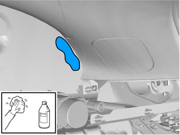
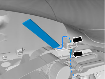
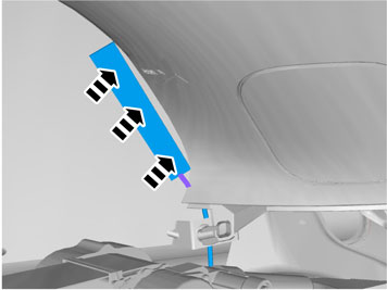
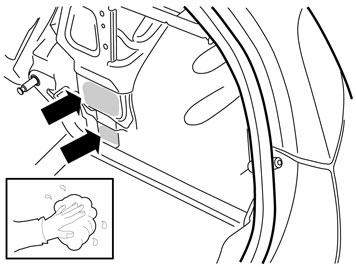
| | Press the antenna onto the inside of the window, as close to the panel edge as possible. Secure the cable to the existing cable harness. Tape the cable harness as illustrated so that it is protected against wear from the panel's guide.
|
|  | | IMG-258670 |
|
| | |
| | | IMG-258619 |
|
| | Disconnect the large connector (1) from the accessory electronic module (AEM). First press in the catch (A). Pull the black locking handle (B) in the direction of the arrow until a click is heard. Disconnect the connector from the accessory electronic module (AEM). Disconnect the connector (2) from the accessory electronic module (AEM).
|
| | | M3702530 |
|
| | Remove: the black catch (1) holding the black switch in place in the connector by pulling in the direction of the arrow. the black switch (2) by inserting a pointed object in the hole in the other end. Press out.
|
| | | M3702955 |
|
| | Note!
The numerical markings on the top and bottom of the black terminal pin are extremely small, so be careful when installing the cable. |
|
| | | IMG-258620 |
|
| | |
| | | IMG-258667 |
|
| | |
|  | | IMG-222282 |
|
| | |
| | | IMG-222283 |
|
| | |
| | | IMG-222284 |
|
| | |
| | | IMG-222285 |
|
| | |
| | | IMG-222286 |
|
| | |
| | | IMG-225262 |
|
| | |
| | | IMG-258665 |
|
| | Connect the green (GN) cable from the kit to terminal 3, and the black (BK) cable to terminal 6 in the six pin connector. Press the secondary catch into place on the black six pin connector.
|
|  | | IMG-258663 |
|
| | Synchronising the transmitter and receiver Connect the negative battery cable in the car. Connect the aerial cable to the receiver unit. Connect the connector to the receiver unit. Within the time interval 1.5 to 5 seconds, press the "OFF" button on the transmitter until the LED goes out.
Synchronisation complete. Note!
Tape up any cable excess from the timer relay and place beside the control module under the insulation. |
|
|  | | IMG-258674 |
|
| | |
| | | IMG-222287 |
|
| | |
|  | | IMG-258675 |
|
| | |
| | |
| | | IMG-242268 |
|
| | |
| | |
|  | | J8504575 |
|
| | |
|  | | J8504577 |
|
| | Removing the sill trim panel from the tailgate: Prize off the four external clips at the front edge/bottom edge of the sill trim panel on the tailgate. Pry up one of the corners of the sill trim panel so that the two clips at that end release. Use a weatherstrip tool. Pull up the sill trim panel so the remaining six clips release. Remove the panel.
|
|  | | J8504578 |
|
| | Removing the rubber seal for the tailgate: Loosen the rubber strip where it covers the right side panel and remove it.
|
|  | | J8504707 |
|
| | Removing the side cushion: Grasp the upper edge of the right-hand side cushion (A). Pull the side cushion forward so that the clips on the reverse release. Slide the side cushion upwards.
Removing the panel at the front/top of the side panel: Remove the screw at the rear edge of the panel at the front/top of the right-hand side panel. Pull the panel upwards so that the four clips on the inside release.
|
|  | | J8504585 |
|
| | Removing the lower panel on the C-post: Carefully pry off the lower panel on the C-post on the right-hand side. Carefully pry at the top edge. Use a plastic weatherstrip tool. Pull the panel on the C-post so that the two upper clips release. Then continue pulling downwards until the last two clips release.
|
|  | | J8504570 |
|
| | Removing the side panel: Fold out the load securing eyelets on the right-hand side panel. Insert a scriber with an angled tip into the holes in the top of the covers (1). Turn the scriber so that the tip engages the reverse of the cover. Pull the covers off. Remove the screws in the load securing eyelets. Remove the screw (2) at the front/top edge of the side panel. Pull off the side panel at the top so that the two clips at the rear/bottom of the side window and the clip at the bottom of the D-pillar release. Disconnect the connector for the 12V socket, if present.
|
|  | | J8504576 |
|
| | |
|  | | J3904767 |
|
| | Applies to cars with Parking Assistance Module (PAM): Remove the parking assistance module (PAM) with cables from behind the right-hand rear wheel arch. If necessary: disconnect any surrounding wiring.
|
|  | | J8504615 |
|
| | |
|  | | IMG-258614 |
|
| | |
|  | | J8504579 |
|
| | |
|  | | IMG-258615 |
|
| | |
|  | | IMG-258616 |
|
| | |
|  | | IMG-258617 |
|
| | |
| | | IMG-257987 |
|
| | |
|  | | IMG-258618 |
|
| | Press the antenna onto the inside of the window, as close to the panel edge as possible. Secure the cable at the existing cable harness.
|
| | | IMG-258619 |
|
| | Disconnect the large connector (1) from the accessory electronic module (AEM). First press in the catch (A). Pull the black locking handle (B) in the direction of the arrow until a click is heard. Disconnect the connector from the accessory electronic module (AEM). Disconnect the connector (2) from the accessory electronic module (AEM).
|
| | | M3702530 |
|
| | Remove: the black catch (1) holding the black switch in place in the connector by pulling in the direction of the arrow. the black switch (2) by inserting a pointed object in the hole in the other end. Press out.
|
| | | M3702955 |
|
| | Note!
The numerical markings on the top and bottom of the black terminal pin are extremely small, so be careful when installing the cable. |
|
| | | IMG-258620 |
|
| | |
| | | IMG-258614 |
|
| | |
| | | IMG-222282 |
|
| | |
| | | IMG-222283 |
|
| | |
| | | IMG-222284 |
|
| | |
| | | IMG-222286 |
|
| | |
| | | IMG-222287 |
|
| | |
| | | IMG-225262 |
|
| | |
| | | IMG-258665 |
|
| | Connect the green (GN) cable from the kit to terminal 3, and the black (BK) cable to terminal 6 in the six pin connector. Press the secondary catch into place on the black six pin connector.
|
| | | IMG-258663 |
|
| | Synchronising the transmitter and receiver Connect the negative battery cable in the car. Connect the aerial cable to the receiver unit. Connect the connector to the receiver unit. Within the time interval 1.5 to 5 seconds, press the "OFF" button on the transmitter until the LED goes out.
Synchronisation complete. Note!
Tape up any cable excess from the timer relay and place beside the control module under the insulation. |
|
|  | | IMG-258664 |
|
| | |
|  | | IMG-258666 |
|
| | |
| | |
| | | IMG-242268 |
|
| | |
| | |
|  | | IMG-221940 |
|
| | |
|  | | IMG-221661 |
|
| | |
|  | | IMG-221960 |
|
| | |
|  | | IMG-221961 |
|
| | Remove: the clip. the screw. the toolbox.
|
|  | | IMG-221962 |
|
| | |
|  | | IMG-242965 |
|
| | |
|  | | IMG-242966 |
|
| | |
|  | | IMG-242967 |
|
| | For cars with emergency release handle in cargo compartment Remove the boot lid's emergency opening handle by pressing out the pin at the eye and then unhooking the wire.
|
|  | | IMG-221966 |
|
| | |
|  | | IMG-221967 |
|
| | |
|  | | IMG-221968 |
|
| | |
|  | | IMG-221969 |
|
| | |
|  | | IMG-221972 |
|
| | |
|  | | IMG-242968 |
|
| | |
|  | | IMG-221974 |
|
| | |
|  | | IMG-242969 |
|
| | |
|  | | IMG-221976 |
|
| | |
|  | | IMG-262684 |
|
| | |
|  | | IMG-262685 |
|
| | |
|  | | IMG-262686 |
|
| | |
| | | IMG-257987 |
|
| | |
|  | | IMG-262687 |
|
| | |
| | | IMG-258619 |
|
| | Disconnect the large connector (1) from the accessory electronic module (AEM). First press in the catch (A). Pull the black locking handle (B) in the direction of the arrow until a click is heard. Disconnect the connector from the accessory electronic module (AEM). Disconnect the connector (2) from the accessory electronic module (AEM).
|
| | | M3702530 |
|
| | Remove: the black catch (1) holding the black switch in place in the connector by pulling in the direction of the arrow. the black switch (2) by inserting a pointed object in the hole in the other end. Press out.
|
| | | M3702955 |
|
| | Note!
The numerical markings on the top and bottom of the black terminal pin are extremely small, so be careful when installing the cable. |
|
| | | IMG-258620 |
|
| | |
|  | | IMG-262688 |
|
| | |
| | | IMG-222282 |
|
| | |
| | | IMG-222283 |
|
| | |
| | | IMG-222284 |
|
| | |
| | | IMG-222286 |
|
| | |
| | | IMG-225262 |
|
| | |
| | | IMG-258665 |
|
| | Connect the green (GN) cable from the kit to terminal 3, and the black (BK) cable to terminal 6 in the six pin connector. Press the secondary catch into place on the black six pin connector.
|
|  | | IMG-262783 |
|
| | Synchronising the transmitter and receiver Connect the negative battery cable in the car. Connect the aerial cable to the receiver unit. Connect the connector to the receiver unit. Within the time interval 1.5 to 5 seconds, press the "OFF" button on the transmitter until the LED goes out.
Synchronisation complete. Note!
Tape up any excess cable and place it beside the control module. |
|
|  | | IMG-262784 |
|
| | |
| | | IMG-222287 |
|
| | |
|  | | IMG-262785 |
|
| | |
| | | IMG-242268 |
|
| | Reinstall: the side panel. stops and attaching braces. the cargo compartment carpeting. the sill panel with lighting. any emergency release. the stop for the boot lid. load holding eyes, torque-tighten the screws with 24 Nm (17 lbf.ft.). the toolbox. the divider.
|