| | |
|  | | R8504436 |
|
| | |
|  | | R8902691 |
|
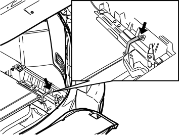
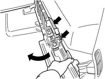
| | If the rear floor hatch has bag holders underneath, the floor hatch is secured by a strap with knob on each short side of the storage box. |
|  | | R8902827 |
|
| | |
|  | | R8504158 |
|
| | |
|  | | R8902823 |
|
| | |
|  | | R8903022 |
|
| | |
|  | | R8902822 |
|
| | |
|  | | R8902820 |
|
| | |
|  | | R8902821 |
|
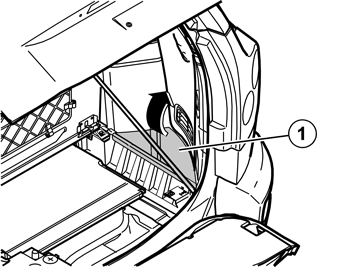
| | Note!
Do not damage the load floor support as it is fragile. |
|
|  | | R8902825 |
|
| | |
|  | | R8902826 |
|
| | |
|  | | R7600433 |
|
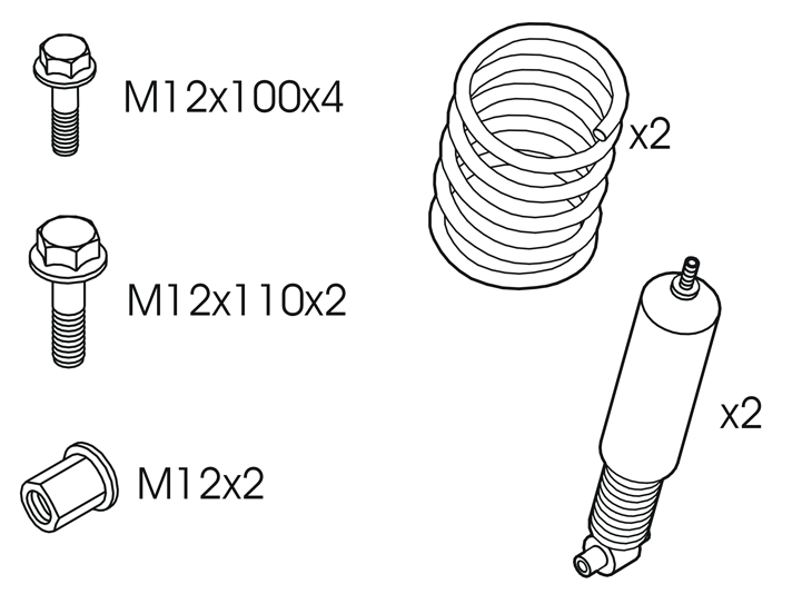
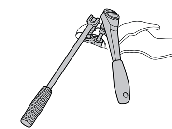
| | Remove the nut for the shock absorber's upper bearing. Use sleeve part no. 9995500 and Torx socket 40 as counterhold. Place the nut to one side, a new panel is in the kit. Repeat steps - for the other side.
|
|  | | R7600440 |
|
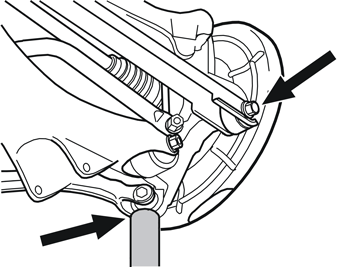
| | Raise the car. Remove the wheels. Remove the lower screw in the shock absorber's mounting at the lower control arm. Place the screw to one side, a new one is in the kit. Remove the shock absorber.
|
|  | | R6500486 |
|
| | |
|  | | R6100358 |
|
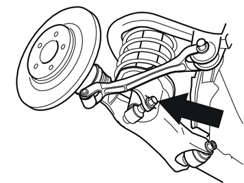
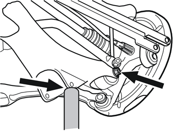
| | Take the workshop lift and position it under the lateral link's rear mounting in the wheel spindle to relieve the load from the screw for the lateral link's front mounting. Remove the screw in the lateral link's front mounting and relieve the load at the same time using the strap and workshop lift. Put away the the screw, new is included in the kit.
|
|  | | R7600439 |
|
| | |
|  | | R7600438 |
|
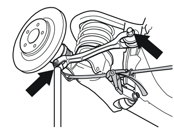
| | Position the workshop lift under the rear mounting eye for the shock absorber's lower mounting, to relieve the load from the screw for the lower control arm's mounting in the wheel spindle. Relieve the load, remove the screw and lower the workshop lift carefully. Put away the the screw, new is included in the kit.
|
|  | | R6500484 |
|
| | |
|  | | R7600437 |
|
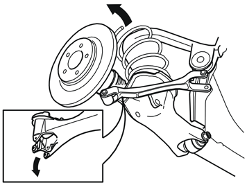
| | Take the new spring from the kit, insert it from above with the wider part of the spring facing down. The control arm may need pushing down slightly to get the spring in place. Position the spring's ends against the relevant stop in the upper mounting and control arm. Take the workshop lift and position it under the rear eyelet for the shock absorber's mounting in the control arm. Carefully push the control arm up into position. Take a new M12x100 screw from the kit and tighten the control arm to the wheel spindle. Do not tighten fully yet.
|
| | | R7600439 |
|
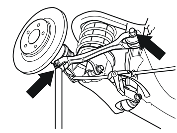
| | Take a new M12x60 screw and nut from the kit for the track rod. Place the track rod's loose end into position. Place the workshop lift under the lateral link's rear mounting in the wheel spindle. Press the wheel spindle up and align the screw in the track rod and wheel spindle. Install the nut, but do not tighten fully yet,
|
|  | | R6100359 |
|
| | Take a new M12x100 screw from the kit for the lateral link's front mounting. Insert the lateral link's front end into position by pushing the wheel spindle up using the workshop lift. Use the lateral link's mounting in the wheel spindle as a lifting point. Adjust to the correct position using the strap and install the new screw. Do not tighten fully yet.
|
|  | | R7600434 |
|
| | |
|  | | R7600435 |
|
| | |
| | Move up the new shock absorber through the lower control arm, spring and up into the mounting in the body. Ensure that the loose bearing does not rotate on the shock absorber and ends up in the wrong position. Take a new M12x110 screw from the kit and tighten the shock absorber. Torque tighten to 80 Nm ( 59 lbf. ft.). Remove the strap and workshop lift. Repeat steps - for the other side.
|
|  | | R7600456 |
|
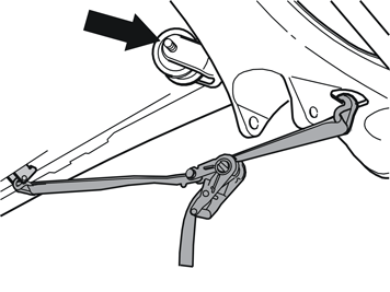
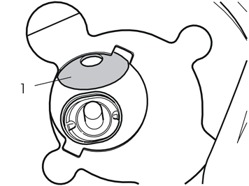
| | Lower the car to almost ground level. Take a jack and position it under the shock absorber's lower mounting and raise slightly. Check that the upper shock absorber bearing is correctly positioned in its upper mounting in the body by moving the loose washer (1) for the bearing that is located there. The bearing must be positioned in the upper mounting as illustrated.
|
|  | | R7600441 |
|
| | When the bearing is correctly positioned, raise further using the jack until the bearing is fully up in the mounting. Pull out the washer and install it on the shock absorber Take a new nut from the kit, install it on the shock absorber and tighten. Torque tighten to 80 Nm (59 lbf. ft.). Use sleeve part no. 999 5500 and Torx socket 40 as counterhold. Remove the jack. Repeat steps - for the other side.
|
|  | | R6500498 |
|
| | |
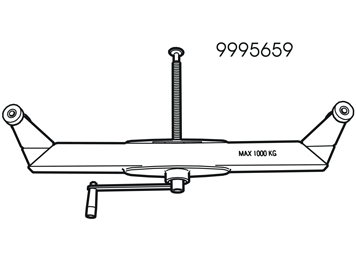
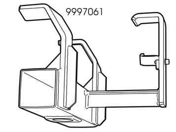
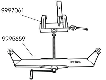
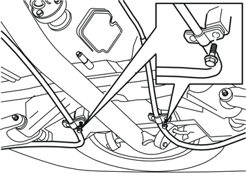
| | Relieving the load from the rear suspension using tensioner 999 5659 Illustration A Tensioner, part no. 999 5659, is used when working with suspension because it is extremely important that the screwed joint to the rubber bushings is tightened in the normal position, i.e. same position as when the car is on the ground with three people in the car and a full tank of fuel. Use the tensioner to relieve the load from the component parts in the suspension when at removal/installation. Illustration B The tool is attached in the subframe itself with mounting part no. 999 7061. This means that the stability of the lift is not affected during work. Illustration C Install the threaded bar on the tensioner (part no. 999 5659). Lift up the tensioner with the threaded bar (part no. 999 5659). Insert the threaded bar into the mounting (part no. 999 7061) from underneath. Take the locking washer with handle and insert it from the side into the mounting (part no. 999 7061) under the threaded screw. Lock the screw in the locking washer and align the locking washer into the mounting.
Note!
The locking washer has a guide pin that must fit the screw. |
|
|  | | R6500490 |
|
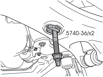
| | Install the two screws, part no. 5470-36, from kit, part no. 998 9761, into the control arms' holes.
|
|  | | R6500497 |
|
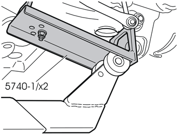
| | Install the rails, part no. 5740-1, modified according to VM-276, on the control arms. Ensure that the rollers are against the rails on both sides of the control arms.
Note!
The tensioner must be applied as far out as possible on the tensioner plates in order to provide the correct lifting force. |
|
|  | | R6500491 |
|
| | |
|  | | N6500390 |
|
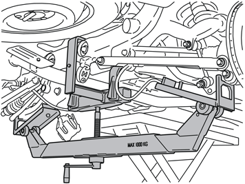
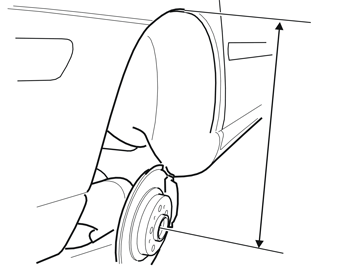
| | Move the control arms up so far that the dimension between the wheel centre and the wing edge is 453 mm (17 13/16"). Torque tighten the screws in the slackened joint as follows: The track rod's mountings in the wheel spindles 80 Nm (59 lbf. ft.) The control arms' lower mountings in the wheel spindles 80 Nm (59 lbf. ft.) The lateral link's front mountings in the body 80 Nm (59 lbf. ft.) Remove the tensioner with component parts. Reinstall the mountings for the parking brake cables in the subframe.
|
|  | | IMG-349166 |
|
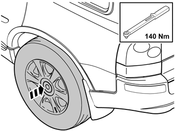
| | Lower the car. Reinstall the wheels. Tighten the wheel bolts alternately and torque tighten to 140 Nm (103 lbf.ft.) Reinstall the covers and the foam rubber seals over the upper shock absorber mountings. Fold the insulation panels and floor mats back. Reset the seats.
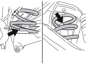
Reinstall: load floor support the jack the side floor hatches the storage boxes the floor hatches.
|
|  | | IMG-275777 |
|
| | Perform wheel alignment. Information available in VIDA under: Repair Clean, check and adjust 6 Suspension, steering 60 general Wheel alignment Wheel angles, check/adjust
|