| | |
| | Read through all of the instructions before starting installation. Notifications and warning texts are for your safety and to minimise the risk of something breaking during installation. Ensure that all tools stated in the instructions are available before starting installation. Certain steps in the instructions are only presented in the form of images. Explanatory text is also given for more complicated steps. In the event of any problems with the instructions or the accessory, contact your local Volvo dealer.
|
| | |
|  | | IMG-363036 |
|
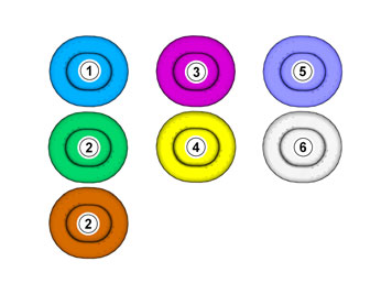
| | Note!
This colour chart displays (in colour print and electronic version) the importance of the different colours used in the images of the method steps. |
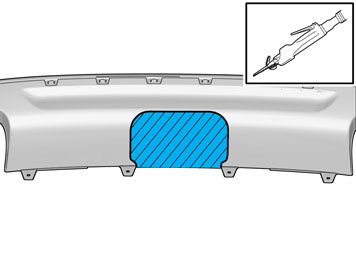
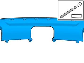
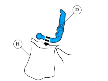
Used for focused component, the component with which you will do something. Used as extra colors when you need to show or differentiate additional parts. Used for attachments that are to be removed/installed. May be screws, clips, connectors, etc. Used when the component is not fully removed from the vehicle but only hung to the side. Used for standard tools and special tools. Used as background color for vehicle components.
|
| | |
|  | | IMG-259752 |
|
| | |
|  | | IMG-259753 |
|
| | |
|  | | IMG-259755 |
|
| | |
|  | | IMG-259754 |
|
| | |
|  | | IMG-379389 |
|
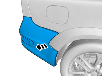
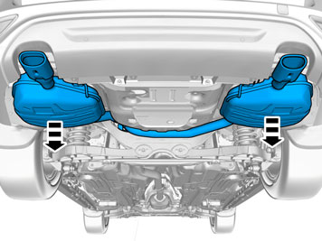
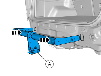
| | Repeat on the other side. |
|  | | IMG-379404 |
|
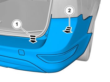
| | Caution!
Push the bumper casing down when removing, so as not to damage the rear lights. |
Note!
This step is easier with two people. |
Repeat on the other side. |
|  | | IMG-379386 |
|
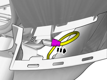
| | Note!
This step is easier with two people. |
Release the connector's catch. Disconnect the connector. |
|  | | IMG-379405 |
|
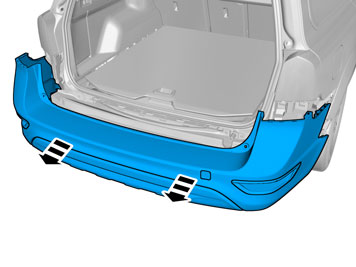
| | Caution!
Place the Bumper Cover on a suitable surface. |
Note!
This step is easier with two people. |
|
|  | | IMG-261414 |
|
| | |
|  | | IMG-259759 |
|
| | |
|  | | IMG-259760 |
|
| | |
|  | | IMG-259761 |
|
| | Remove the screws. On both sides. |
|  | | IMG-377019 |
|
| | |
|  | | IMG-377020 |
|
| | Caution!
Take extra care not to damage the wiring harnesses. |
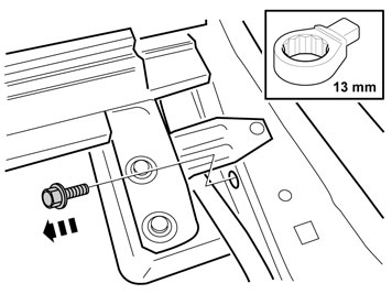
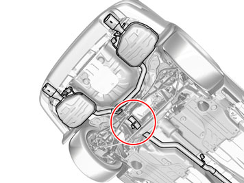
Remove the screw. |
|  | | IMG-259763 |
|
| | |
| | |
| | Vehicles without spare wheel |
|  | | IMG-260410 |
|
| | Caution!
Make sure not to damage wiring, hoses or other components. |
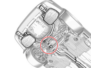
Measure and mark as illustrated. Deburr the hole edges. |
|  | | IMG-378041 |
|
| | Install the screw. Install the nut. |
|  | | IMG-378042 |
|
| | |
| | |
| | Vehicles with double Exhaust End Pipes and AWD |
|  | | IMG-378179 |
|
| | |
|  | | IMG-378176 |
|
| | |
|  | | IMG-260846 |
|
| | |
| | Vehicles with Double Exhaust End Pipes and 2WD |
|  | | IMG-378201 |
|
| | |
|  | | IMG-378200 |
|
| | |
| | |
|  | | IMG-259825 |
|
| | |
|  | | IMG-378203 |
|
| | Note!
This step is easier with two people. |
|
|  | | IMG-260849 |
|
| | |
|  | | IMG-378129 |
|
| | |
|  | | IMG-364281 |
|
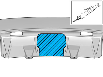
| | Measure and mark as illustrated. Remove the tape. Repeat on the other side. |
|  | | IMG-260852 |
|
| | Caution!
Make sure that the surface is clean and free of foreign material. |
Clean the surface. Repeat on the other side. |
| | |
|  | | IMG-378204 |
|
| | |
|  | | IMG-378464 |
|
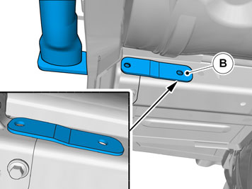
| | Repeat on the other side. |
|  | | IMG-378465 |
|
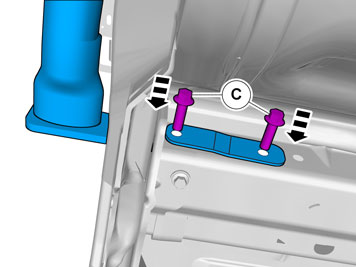
| | Note!
This step is easier with two people. |
Note!
Only tighten the bolts finger tight at this stage. |
Install the screws. Repeat on the other side. |
|  | | IMG-378466 |
|
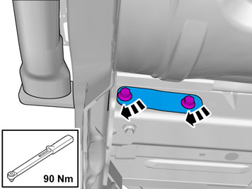
| | Repeat on the other side. |
|  | | IMG-378467 |
|
| | Repeat on the other side. |
| | |
|  | | IMG-378136 |
|
| | |
|  | | IMG-261083 |
|
| | |
|  | | IMG-378220 |
|
| | |
|  | | IMG-282946 |
|
| | Measure and mark as illustrated. |
|  | | IMG-378212 |
|
| | Note!
This step is easier with two people. |
|
|  | | IMG-282963 |
|
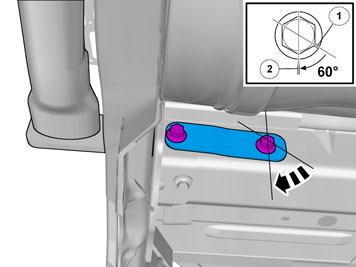
| | Install the screws.
Tightening torque: M10
, 50 Nm
|
| | Vehicles with double Exhaust End Pipes and AWD |
|  | | IMG-260865 |
|
| | |
| | |
|  | | IMG-378218 |
|
| | Warning!
Make sure that there are no leaks. |
Note!
Ensure that the exhaust clamp cannot come into contact with surrounding parts during operation. |
|
| | Vehicles with Single Exhaust End Pipe and AWD |
| | |
|  | | IMG-259824 |
|
| | |
|  | | IMG-259827 |
|
| | |
|  | | IMG-260867 |
|
| | |
|  | | IMG-260868 |
|
| | Note!
Always use new seals, screws and nuts. |
Remove the nuts. |
|  | | IMG-260869 |
|
| | Caution!
Make sure that the exhaust flexible pipe is not forcibly bent or twisted. |
|
|  | | IMG-260870 |
|
| | |
|  | | IMG-260871 |
|
| | |
| | | IMG-364281 |
|
| | Measure and mark as illustrated. Remove the tape. Repeat on the other side. |
| | | IMG-260852 |
|
| | Caution!
Make sure that the surface is clean and free of foreign material. |
Clean the surface. Repeat on the other side. |
| | |
| | | IMG-378204 |
|
| | |
| | | IMG-378464 |
|
| | Repeat on the other side. |
| | | IMG-378465 |
|
| | Note!
This step is easier with two people. |
Note!
Only tighten the bolts finger tight at this stage. |
Install the screws. Repeat on the other side. |
| | | IMG-378466 |
|
| | Repeat on the other side. |
|  | | IMG-378468 |
|
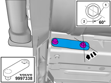
| | Repeat on the other side.
Use special tool: T9997338, Extension rod
|
| | |
|  | | IMG-260923 |
|
| | |
| | | IMG-260867 |
|
| | |
|  | | IMG-378222 |
|
| | Note!
Always use new seals, screws and nuts. |
Install the nuts |
|  | | IMG-259871 |
|
| | Install the screw.
Tightening torque: M10
, 50 Nm
|
|  | | IMG-259873 |
|
| | |
| | Vehicles with Single Exhaust End Pipe and 2WD |
| | |
|  | | IMG-259823 |
|
| | |
| | | IMG-259827 |
|
| | |
| | Vehicles with 4 cyl diesel engine |
|  | | IMG-259836 |
|
| | Caution!
Make sure that the exhaust flexible pipe is not forcibly bent or twisted. |
Note!
Always use new seals, screws and nuts. |
Remove the nuts. |
| | Vehicles with 4-cyl gasoline engine |
|  | | IMG-259837 |
|
| | Caution!
Make sure that the exhaust flexible pipe is not forcibly bent or twisted. |
Note!
Always use new seals, screws and nuts. |
Remove the nuts. |
| | Vehicles with 5-cyl diesel engine |
|  | | IMG-259838 |
|
| | Caution!
Make sure that the exhaust flexible pipe is not forcibly bent or twisted. |
Remove the nuts. Always use new seals, screws and nuts. |
|  | | IMG-259829 |
|
| | |
|  | | IMG-260925 |
|
| | |
| | | IMG-364281 |
|
| | Measure and mark as illustrated. Remove the tape. Repeat on the other side. |
| | | IMG-260852 |
|
| | Caution!
Make sure that the surface is clean and free of foreign material. |
Clean the surface. Repeat on the other side. |
| | |
| | | IMG-378204 |
|
| | |
| | | IMG-378464 |
|
| | Repeat on the other side. |
| | | IMG-378465 |
|
| | Note!
This step is easier with two people. |
Note!
Only tighten the bolts finger tight at this stage. |
Install the screws. Repeat on the other side. |
| | | IMG-378466 |
|
| | Repeat on the other side. |
| | | IMG-378468 |
|
| | Repeat on the other side.
Use special tool: T9997338, Extension rod
|
| | |
|  | | IMG-260929 |
|
| | |
|  | | IMG-259865 |
|
| | |
| | Vehicles with 4 cyl diesel engine |
|  | | IMG-378224 |
|
| | Note!
Always use new seals, screws and nuts. |
Install the nuts |
| | Vehicles with 4-cyl gasoline engine |
|  | | IMG-378225 |
|
| | Note!
Always use new seals, screws and nuts. |
Install the nuts |
| | Vehicles with 5-cyl diesel engine |
| | | IMG-378222 |
|
| | Note!
Always use new seals, screws and nuts. |
Install the nuts |
| | | IMG-259871 |
|
| | Install the screw.
Tightening torque: M10
, 50 Nm
|
|  | | IMG-259874 |
|
| | |
| | |
|  | | IMG-259875 |
|
| | Use: , Rust inhibitor, low viscosity
Repeat on the other side. |
|  | | IMG-259876 |
|
| | Install the screws. Repeat on the other side. |
|  | | IMG-282983 |
|
| | Caution!
Take extra care not to damage the wiring harnesses. |
Install the screw. |
|  | | IMG-364322 |
|
| | |
|  | | IMG-260746 |
|
| | |
|  | | IMG-259881 |
|
| | |
| | |
|  | | IMG-378262 |
|
| | |
|  | | IMG-377452 |
|
| | |
|  | | IMG-378488 |
|
| | |
|  | | IMG-378238 |
|
| | |
|  | | IMG-378239 |
|
| | |
|  | | IMG-378241 |
|
| | |
|  | | IMG-378524 |
|
| | |
|  | | IMG-378523 |
|
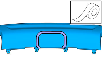
| | Apply tape to the other side, opposite the marking lines. |
|  | | IMG-378522 |
|
| | |
|  | | IMG-378525 |
|
| | |
|  | | IMG-377070 |
|
| | Install tow bar connector and wiring harness according to installation instruction: Towbar, Wiring and Control Unit. Reinstall the removed parts in reverse order. |
| | Vehicles without spare wheel |
|  | | IMG-378068 |
|
| | |
|  | | IMG-226145 |
|
| | |
|  | | IMG-226147 |
|
| | |
| | Vehicles with spare wheel |
| | | IMG-378068 |
|
| | |
|  | | IMG-226148 |
|
| | |
|  | | IMG-226150 |
|
| | |
| | |
|  | | IMG-260445 |
|
| | Take the label from the kit and attach it to the underneath of the cargo compartment mat as illustrated. Attach the four corners of the label using staples. |
|  | | IMG-261415 |
|
| | |
|  | | IMG-226909 |
|
| | |
|  | | IMG-227105 |
|
| | |
| | |
|  | | IMG-260447 |
|
| | |