| | |
|  | | J8504730 |
|
| | Preparations Open the glove compartment lid. Remove the panel on the right-hand end of the dashboard by carefully prying it loose all around with a weatherstrip tool, until the three clips on the inside release.
Note!
Do not damage the dashboard. |
|
|  | | J8504731 |
|
| | Remove the sill trim panel of the right front door by pulling it starting at the front edge until the clip releases. Continue rearward until the remaining clips on the underside have released. Unhook the it from the B-post panel.
|
|  | | J8504732 |
|
| | Move the carpeting aside to access the grommet in the firewall and install the passenger compartment connector. Unscrew the clip holding the insulating mat to the body. Put it aside. It will not be used again.
|
|  | | J8000359 |
|
| | |
|  | | J2900337 |
|
| | |
| | |
|  | | D3601932 |
|
| | Installing the junction connector |
|  | | J2900302 |
|
| | |
|  | | J2900296 |
|
| | Tighten the junction connector at the bracket in the position illustrated. Use the screw, toothed washer and nut from the kit. The bracket must be parallel to the length of the junction connector. Position (1) cable for the engine block heater Position (2) cable for the passenger compartment connector Position (3) cable from the front engine block heater socket.
|
|  | | J2900371 |
|
| | Detach the cable from the front intake and engine heater from its clamps/clips to facilitate installation of the passenger compartment junction connector. Connect the front intake cable (1) to the junction connector and press the cable splice together securely.
|
|  | | J2900372 |
|
| | |
|  | | J2900373 |
|
| | Connect the engine heater cable (1). Connect the cable (2) from the kit to the passenger compartment connector. Press the cables securely into the junction connector
|
|  | | J2900374 |
|
| | |
|  | | J2900359 |
|
| | |
|  | | J2900338 |
|
|  | | J2900375 |
|
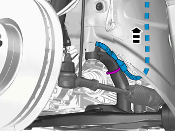
| | Illustration A Illustration B Adjust the position of the junction connector so that the measurement is 135 mm (5 5/16"). Tighten the hose clamp securely. Reinstall the cables of the engine heater and front intake in their clamps.
|
| | |
|  | | IMG-360268 |
|
| | |
|  | | IMG-360277 |
|
| | Install 1 clip on the side of the battery box. Guide the cable up to the top of the engine compartment to the position illustrated. Install three clips from the kit on the front edge of the panel above the windscreen wiper motor.
Note!
The cable must not be clamped in so that it is in direct contact with AC, fuel or brake pipes. |
|
|  | | J2900382 |
|
|  | | J2900316 |
|
| | Illustration A Illustration B |
|  | | IMG-360285 |
|
| | |
|  | | J2900384 |
|
| | |
|  | | J2900379 |
|
| | |
|  | | J2900385 |
|
| | Grease the rubber grommet with low-temperature grease part no. 1161417 so that the connector slides through more easily. Insert the passenger compartment connector cable through the rubber grommet and into the passenger compartment. Guide all excess cable into the passenger compartment. Slide the heat shield toward the rubber grommet in the firewall and clamp it with the tie strap from the kit. Reinstall the engine splash guard. Remount the wheel and tighten the lug bolts to 90 Nm (66 lbf.ft.).
|
|  | | J2900363 |
|
| | |
| | |
|  | | J2900364 |
|
| | Installing the passenger compartment connector socket Move aside the insulating mat to drill holes for the passenger compartment connector bracket. Clean away sealant where one corner of the bracket will sit. Fit the bracket from the kit on the pin of the insulating mat's clip. Use the plastic nut from the kit. Align the bracket so that its edge (1) is parallet to the edge (2) in the front edge of the door opening. Drill the hole (3) in the body through the bracket using a Ø 3.5 mm (9/64") bit. Deburr the hole edges and apply anti-corrosion agent to them. Secure the bracket using a plastic nut bolt from the kit.
|
|  | | J2900365 |
|
| | |
|  | | J2900366 |
|
| | |
|  | | J2900367 |
|
| | |
|  | | J2900368 |
|
| | Secure the passenger compartment connector to the bracket using screws from the kit. Reinstall the sill trim panel in the right-hand front door. Reinstall the right end panel of the dashboard.
|