| | |
| | Read through all of the instructions before starting installation. Notifications and warning texts are for your safety and to minimise the risk of something breaking during installation. Ensure that all tools stated in the instructions are available before starting installation. Certain steps in the instructions are only presented in the form of images. Explanatory text is also given for more complicated steps. In the event of any problems with the instructions or the accessory, contact your local Volvo dealer.
|
| | |
| | When installing, the car must retain a temperature of 20 degrees C. |
| | |
|  | | IMG-363036 |
|
| | Note!
This colour chart displays (in colour print and electronic version) the importance of the different colours used in the images of the method steps. |
Used for focused component, the component with which you will do something. Used as extra colors when you need to show or differentiate additional parts. Used for attachments that are to be removed/installed. May be screws, clips, connectors, etc. Used when the component is not fully removed from the vehicle but only hung to the side. Used for standard tools and special tools. Used as background color for vehicle components.
|
| | |
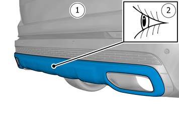
| | Vehicles WITH BOTH Parking assistance (PAS) AND Foot movement detection (FMDM) |
|  | | IMG-242268 |
|
| | Note!
Risk of mix-up! Check that correct software is chosen for download. |
Download software (application) for the accessory's function according to the service information in VIDA. Order and download software according to: 31414746
|
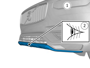
| | Vehicles with JUST Parking assistance (PAS), WITHOUT Foot movement detection (FMDM) |
| | | IMG-242268 |
|
| | Note!
Risk of mix-up! Check that correct software is chosen for download. |
Download software (application) for the accessory's function according to the service information in VIDA. Order and download software according to: 31414665
|
| | |
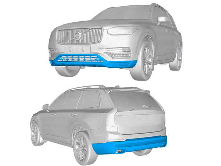
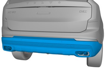
|  | | IMG-396886 |
|
| | |
| | |
| | |
|  | | IMG-392964 |
|
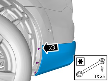
| | Note!
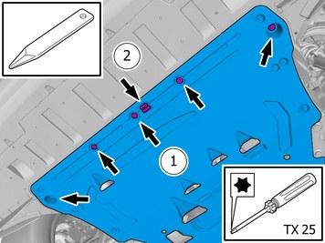
The screws are to be reused. |
Remove the screws. On both sides. |
|  | | IMG-392958 |
|
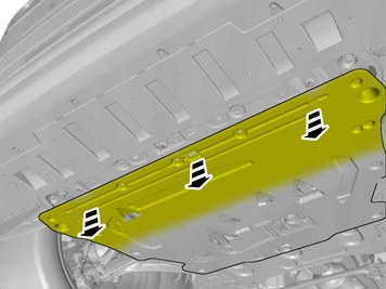
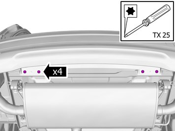
| | Remove the screws. Loosen the clip. |
|  | | IMG-393125 |
|
| | |
|  | | IMG-387143 |
|
| | |
|  | | IMG-397010 |
|
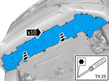
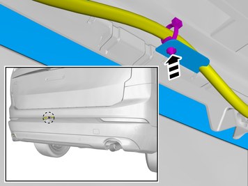
| | Remove the screws. Remove the marked part. |
|  | | IMG-397035 |
|
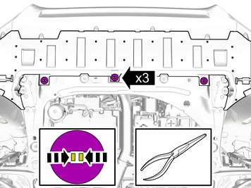
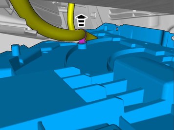
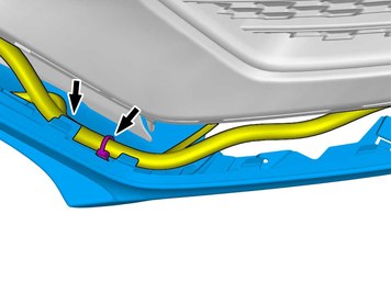
| | Remove the cable harness clips. |
|  | | IMG-397036 |
|
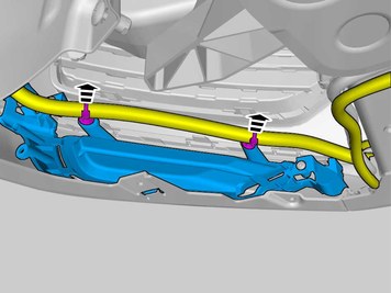
| | Remove the cable harness clips. |
|  | | IMG-397037 |
|
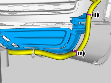
| | Remove the cable harness clips. |
|  | | IMG-393134 |
|
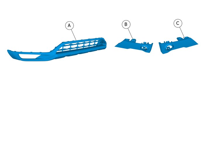
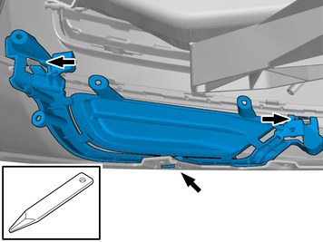
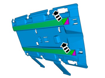
| | Remove the marked part. The part is to be reused. On both sides. |
| | Vehicles with Front Fog Lamps |
|  | | IMG-392968 |
|
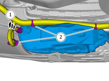
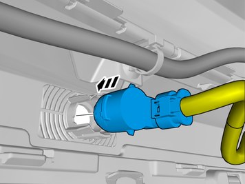
| | Disconnect the connector. Remove the cable harness clips. |
|  | | IMG-397054 |
|
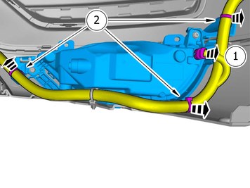
| | Disconnect the connector. Remove the cable harness clips. |
|  | | IMG-393126 |
|
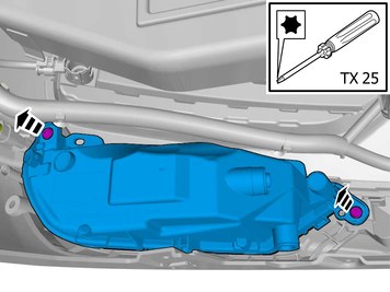
| | Remove the screws. Remove the marked part. The part is to be reused. On both sides. |
|  | | IMG-392972 |
|
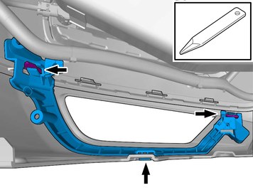
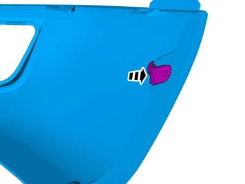
| | Release the catches. Remove the marked part. The part is to be reused. On both sides. |
| | Vehicles with parking assistance |
|  | | IMG-393127 |
|
| | Remove the marked part. Disconnect the connector. On both sides. |
|  | | IMG-393128 |
|
| | Release the catches. Remove the marked part. The part is to be reused. On both sides. |
| | |
|  | | IMG-383170 |
|
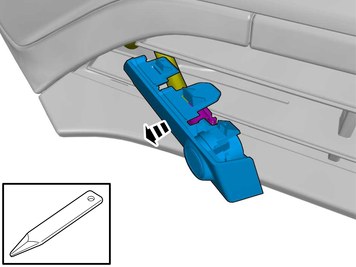
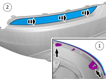
| | Fold marked part aside. Remove the part carefully On both sides. |
|  | | IMG-396314 |
|
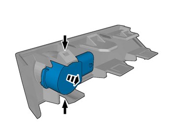
| | Loosen the clips. The part is to be reused. |
|  | | IMG-383194 |
|
| | Remove the marked part. The part is not to be reused. |
|  | | IMG-393322 |
|
| | Remove the cable harness clips. Repeat on the other side. |
| | |
|  | | IMG-396316 |
|
| | Install the clip(s). On both sides. |
|  | | IMG-393130 |
|
| | Install component that comes with the accessory kit. |
| | | IMG-393322 |
|
| | Fasten the wiring harness using the existing clips. On both sides. |
| | Vehicles with parking assistance |
|  | | IMG-397090 |
|
| | Remove the marked part. On both sides. Use: Air-powered air saw
|
|  | | IMG-393131 |
|
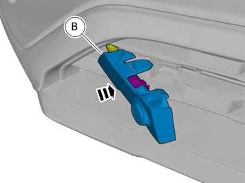
| | Reinstall the removed part. |
|  | | IMG-393132 |
|
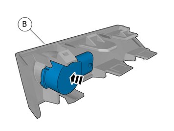
| | Install component that comes with the accessory kit. Connect the connector. |
|  | | IMG-393324 |
|
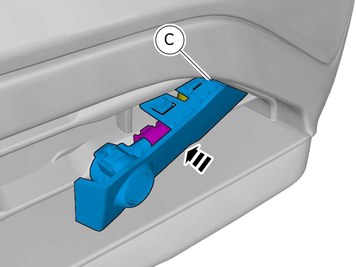
| | Reinstall the removed part. |
|  | | IMG-393323 |
|
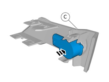
| | Install component that comes with the accessory kit. Connect the connector. |
|  | | IMG-377070 |
|
| | Reinstall the removed parts in reverse order. |
| | |
|  | | IMG-396894 |
|
| | |
| | |
|  | | IMG-383914 |
|
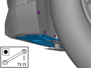
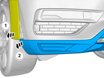
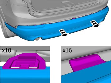
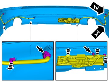
| | Remove the screws. On both sides. |
|  | | IMG-381901 |
|
| | |
|  | | IMG-383913 |
|
| | |
|  | | IMG-392936 |
|
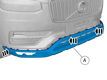
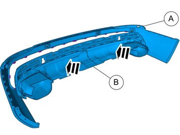
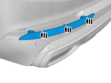
| | Release the catches. On both sides. |
|  | | IMG-396385 |
|
| | |
|  | | IMG-392940 |
|
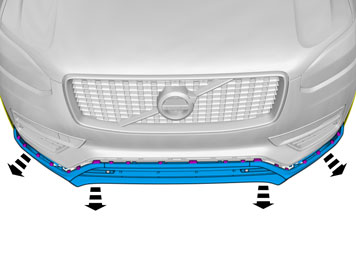
| | Note!
This step is easier with two people. |
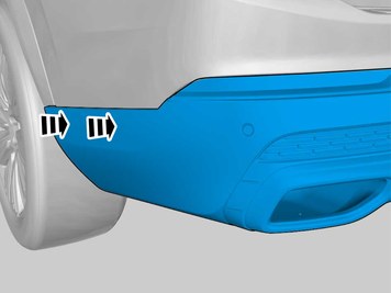
Remove the marked part. |
|  | | IMG-397189 |
|
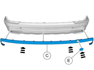
| | Remove the clips. The part is to be reused. On both sides. |
|  | | IMG-397881 |
|
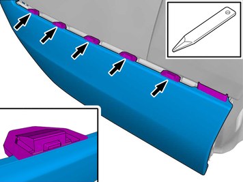
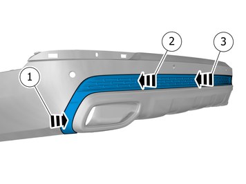
| | Release the catches. Remove the marked part.
Repeat on the other side. The part is not to be reused. |
|  | | IMG-397885 |
|
| | Caution!
The part is to be reused. |
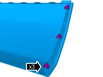
Release the catches. Remove the marked part.
Repeat on the other side. |
| | |
|  | | IMG-383969 |
|
| | |
| | Vehicles with Foot movement detection (FMDM) |
|  | | IMG-395851 |
|
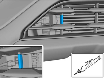
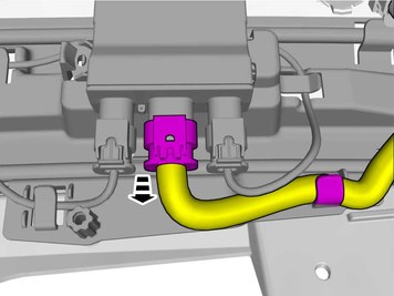
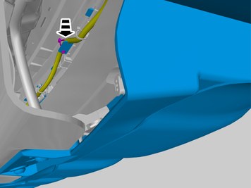
| | Disconnect the connector. |
|  | | IMG-397041 |
|
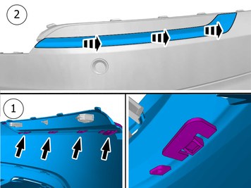
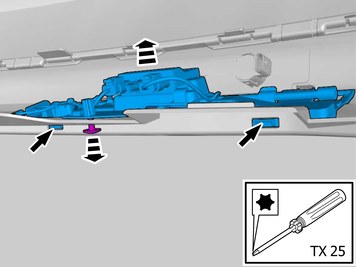
| | Loosen the screws. Release the catches. Remove the marked part. The part is to be reused. |
| | Vehicles with parking assistance |
|  | | IMG-395840 |
|
| | Note!
Do not remove the connectors. |
Remove the cable tie(s). Remove the part carefully Repeat on the other side. |
|  | | IMG-406367 |
|
| | Note!
Do not remove the connectors. |
Remove the cable tie(s). Remove the part carefully Repeat on the other side. |
| | |
|  | | IMG-397092 |
|
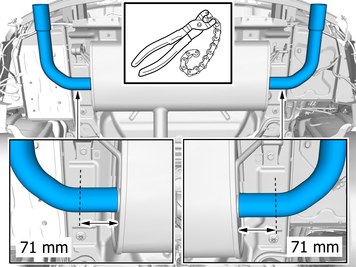
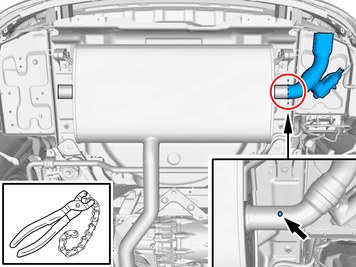
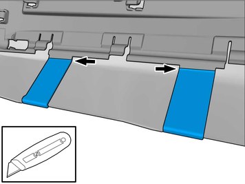
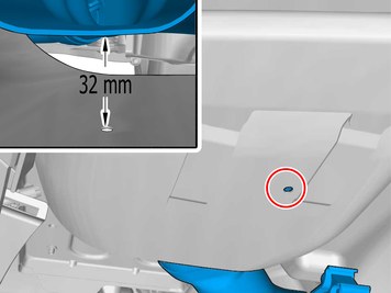
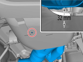
| | Measure and mark as illustrated. Remove the marked detail/details. Use: Pipe cutter
|
| | Vehicles with actuator, early version |
|  | | IMG-397091 |
|
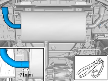
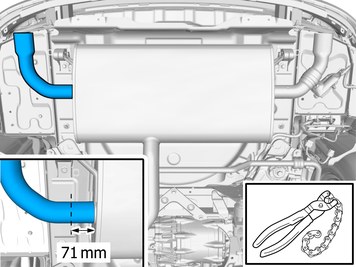
| | Measure and mark as illustrated. Remove the marked part. Use: Pipe cutter
|
|  | | IMG-392927 |
|
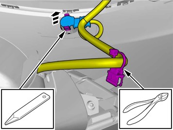
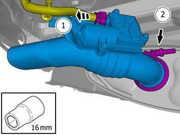
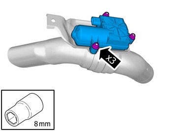
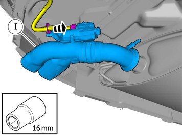
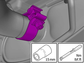
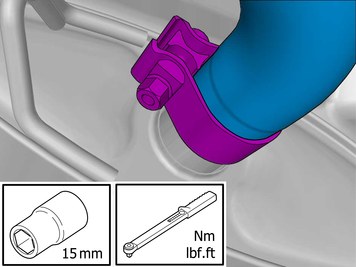
| | Disconnect the connector. Loosen the nut. Remove the marked part. |
|  | | IMG-443653 |
|
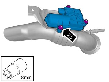
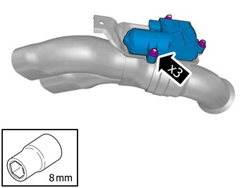
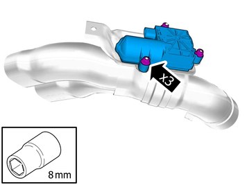
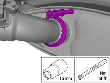
| | Remove the nuts. Remove the marked part. The part is to be reused. |
| | Vehicles with actuator, late version |
|  | | IMG-444301 |
|
| | Measure and mark as illustrated. Remove the marked part. Use: Pipe cutter
|
|  | | IMG-443657 |
|
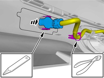
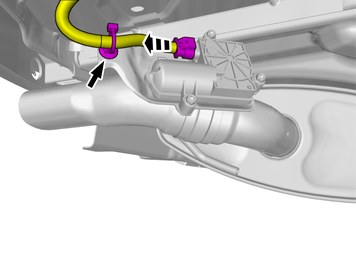
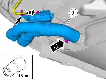
| | Disconnect the connector. Loosen the clip. |
|  | | IMG-444310 |
|
| | Locate relevant marking. Remove the marked part. Use: Pipe cutter
|
|  | | IMG-443659 |
|
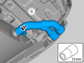
| | Remove the nuts. Remove the marked part. The part is to be reused. |
| | |
| | |
|  | | IMG-397104 |
|
| | Note!
Do not fully tighten the nut yet. |
Install component that comes with the accessory kit. Tighten the nut. |
| | |
|  | | IMG-397121 |
|
| | Note!
Do not fully tighten the nut yet. |
Install component that comes with the accessory kit. Tighten the nut. |
| | Vehicles with actuator, early version |
|  | | IMG-445316 |
|
| | |
|  | | IMG-445315 |
|
| | Reinstall the removed part. Tighten the nuts.
Tightening torque: Actuator, to Exhaust system
, 5 Nm
|
|  | | IMG-392925 |
|
| | Caution!
Be extra careful when removing or installing this component. |
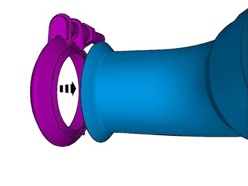
Reinstall the removed part. |
|  | | IMG-397111 |
|
| | Note!
Do not fully tighten the nut yet. |
Install component that comes with the accessory kit. Tighten the nut. Connect the connector. Install the clip(s). |
| | Vehicles with actuator, late version |
|  | | IMG-445317 |
|
| | |
|  | | IMG-443713 |
|
| | Reinstall the removed part. Tighten the nuts.
Tightening torque: Actuator, to Exhaust system
, 5 Nm
|
|  | | IMG-443790 |
|
| | Note!
Do not fully tighten the nut yet. |
Install component that comes with the accessory kit. Tighten the nut. Connect the connector. Install the clip(s). |
| | |
|  | | IMG-384344 |
|
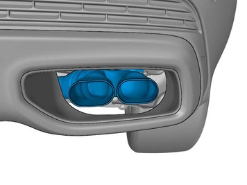
| | Install component that comes with the accessory kit. |
|  | | IMG-384347 |
|
| | Install component that comes with the accessory kit. |
|  | | IMG-401050 |
|
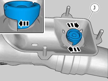
| | Note!
Make sure to follow the sequence indicated. |
Repeat on the other side. |
| | Vehicles with folding towbar |
|  | | IMG-400604 |
|
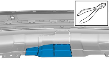
| | Cut following the dotted lines. |
| | Vehicles with fixed towbar |
|  | | IMG-400608 |
|
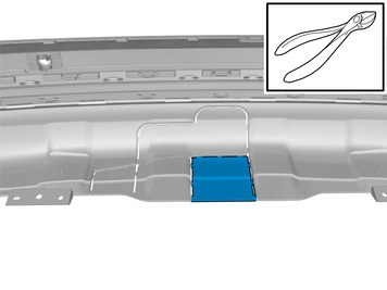
| | Cut following the dotted lines. |
| | Vehicles with towbar, Hitch |
|  | | IMG-400605 |
|
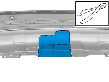
| | Cut following the dotted lines. |
| | Vehicles with Foot movement detection (FMDM) |
|  | | IMG-397138 |
|
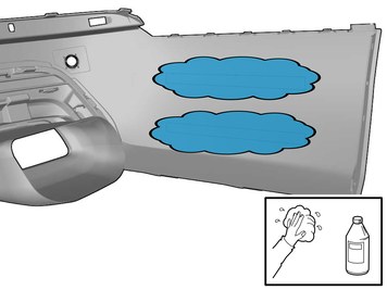
| | Clean the surface. Use: 1161721, Cleaning agent
|
| | | IMG-397138 |
|
| | Apply a thin and even layer. Use: 1161727, Primer
|
|  | | IMG-384168 |
|
| | Remove the protective film. |
|  | | IMG-384148 |
|
| | Hint
Press and apply pressure to the part over the tape for at least 20 seconds. |
Install component that comes with the accessory kit. |
|  | | IMG-384288 |
|
| | |
| | |
|  | | IMG-406368 |
|
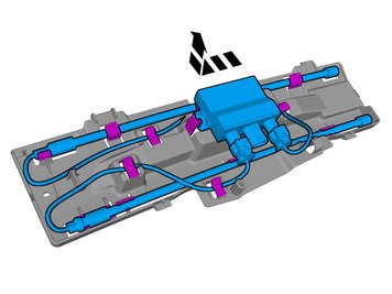
| | Note!
Do not remove the connectors. |
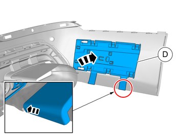
Remove the marked part. The part is to be reused. |
| | |
|  | | IMG-384394 |
|
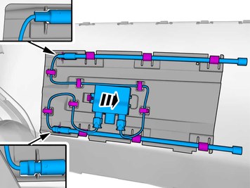
| | Note!
Make sure that the connection/connections point downwards. |
Reinstall the removed part. Position/route the cables as illustrated. |
| | |
|  | | IMG-406405 |
|
| | |
|  | | IMG-384804 |
|
| | |
|  | | IMG-406400 |
|
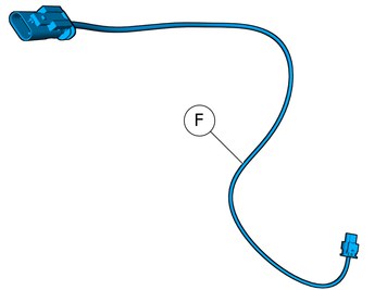
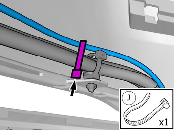
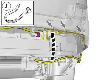
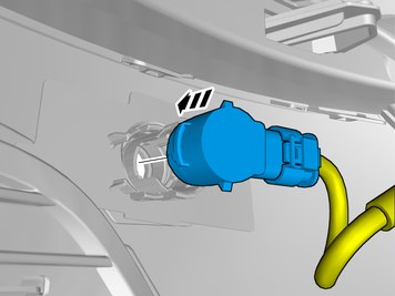
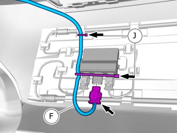
| | Install component that comes with the accessory kit. Connect the connector. Route the wire adjacent to existing wirings. Tighten the cable ties. |
|  | | IMG-406403 |
|
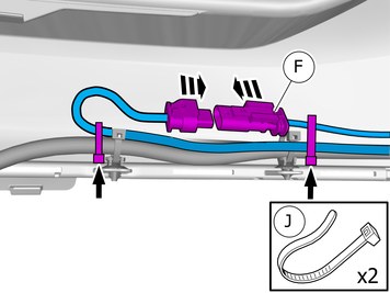
| | Route the wire adjacent to existing wirings. Tighten the cable tie. |
| | Vehicles with parking assistance |
|  | | IMG-395885 |
|
| | Route the wire adjacent to existing wirings. Tighten the cable ties. On both sides. |
|  | | IMG-406410 |
|
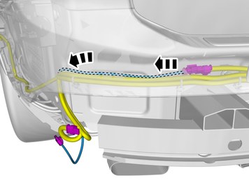
| | Note!
This step is easier with two people. |
Place the component where indicated in the graphic. |
|  | | IMG-406406 |
|
| | Reinstall the removed part. Repeat on the other side. |
|  | | IMG-406408 |
|
| | Reinstall the removed part. Repeat on the other side. |
| | |
|  | | IMG-393101 |
|
| | Note!
This step is easier with two people. |
|
| | | IMG-397189 |
|
| | Reinstall the clips. On both sides. |
|  | | IMG-393100 |
|
| | Repeat on the other side. |
|  | | IMG-397890 |
|
| | Reinstall the removed part. Repeat on the other side. |
| | | IMG-383914 |
|
| | Reinstall the screws. On both sides. |
|  | | IMG-393105 |
|
| | Reinstall the removed part. |
| | | IMG-381901 |
|
| | |
| | Vehicles with Foot movement detection (FMDM) |
|  | | IMG-420100 |
|
| | Position/route the cable harness as illustrated. Connect the connector. Tighten the cable ties. |
| | |
| | |
|  | | IMG-393095 |
|
| | |
|  | | IMG-396589 |
|
| | |
|  | | IMG-393088 |
|
| | Tighten to the value stated.
Tightening torque: M10
, 50 Nm
|
|  | | IMG-393085 |
|
| | |
|  | | IMG-396585 |
|
| | |
| | |
|  | | IMG-393097 |
|
| | Tighten to the value stated.
Tightening torque: M10
, 50 Nm
|
| | Vehicles with actuator, early version |
|  | | IMG-393090 |
|
| | Tighten the nut.
Tightening torque:
,
|
| | Vehicles with actuator, late version |
| | | IMG-393097 |
|
| | Tighten to the value stated.
Tightening torque: M10
, 50 Nm
|
| | |
|  | | IMG-400598 |
|
| | Caution!
Make sure that the surface is clean and free of foreign material. |
Wax the component indicated. |
|  | | IMG-400599 |
|
| | Caution!
Make sure that the surface is clean and free of foreign material. |
Wax the component indicated. |
| | |
|  | | IMG-434130 |
|
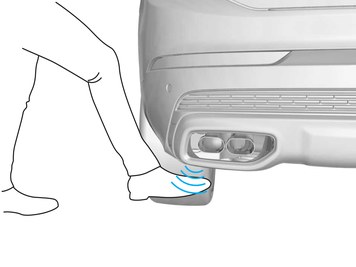
| | Note!
Make sure that trunk lid is only opened by a foot movement under the car. |
Check for correct operation. |