| | |
|  | | J8504553 |
|
| | Applies to the S40 Preparations |
|  | | J8504552 |
|
| | |
|  | | J8504554 |
|
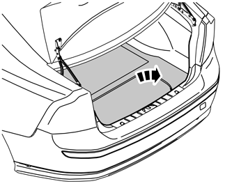
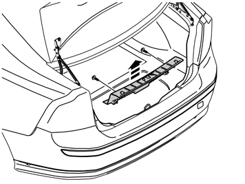
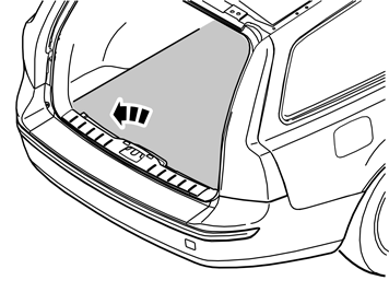
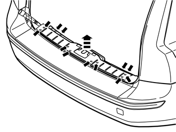
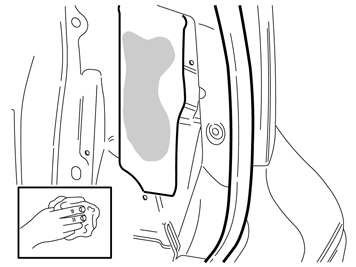
| | Unscrew the two external clips at the front edge/bottom edge of the sill trim panel on the tailgate. Pry up one of the corners of the sill trim panel using a weatherstrip tool so that the two clips at that end release. Pull up the sill trim panel at the other end so that the remaining two clips release. Remove the sill trim panel. Detach the rubber strip where it covers the right-hand side panel in the tailgate opening.
|
|  | | J8504691 |
|
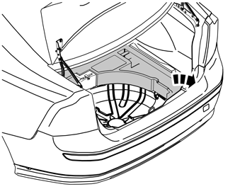
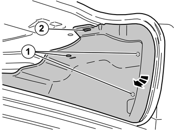
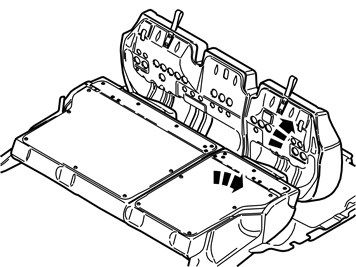
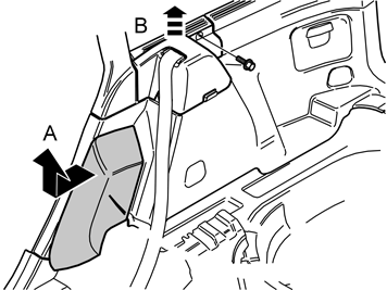
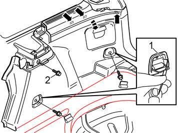
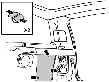
| | Remove the three clips (1) that hold the right-hand side panel in the bodywork. Unhook the side panel from the mounting (2) on the underneath of the parcel shelf. Fold out the rear edge of the side panel from the bodywork. At the same time unhook the side panel from the rear load securing eyelet. If the car has a 12V socket in the side panel, disconnect the connector from this socket (if applicable). Fold out the side panel to access the space in the rear of the wheel arch.
|
| | |
|  | | IMG-271563 |
|
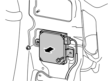
| | Installing the control module |
|  | | IMG-226726 |
|
| | |
|  | | IMG-222283 |
|
| | |
|  | | IMG-222282 |
|
| | |
|  | | IMG-271592 |
|
| | |
|  | | IMG-271591 |
|
| | |
|  | | IMG-271590 |
|
| | |
|  | | IMG-271583 |
|
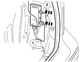
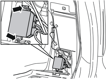
| | Connect the connector from the wiring to the control module. Press the control module on the rear display screen in such a way that the wiring connector is not located at the edge of the lower edge of the display screen. Also check that the module's rear edge is not too close to the body edge.
|
|  | | IMG-271584 |
|
|  | | J3703684 |
|
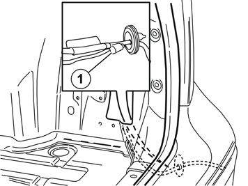
| | Illustration A Look for the pre-routed 2–pin gray connector (1) for the control module power supply, and the pre-routed 5–pin green connector (2) for signals to the control module. The connectors are clamped at the front edge of the large hole in the side of the bodywork.
Note!
If the car is equipped with an Accessory Electronic Module (AEM) then the green connector is not clamped but hangs loose. |
Connect the connectors to the control module.
Illustration B Applies to cars from CH 45000-, with Parking Assistance Module (PAM) Detach the green (GN) five pin connector (1) which is taped at the Parking Assistance Module (PAM) cable's rubber grommet. Plug the green connector into the Trailer module wiring, (TRM).
|
|  | | IMG-269603 |
|
| | Applies to S40s manufactured after w720 Pull up the catch on the cover on the fuse box in the engine compartment. Pull up the cover and remove it.
|
|  | | IMG-269623 |
|
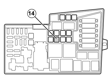
| | Applies to S40s manufactured after w720 Take a 40A fuse from the kit and install it in terminal 14 in fuse holder. Reinstall the cover.
|
| | Reinstall the side panel. If the car has a 12V socket, connect the connector to this. Reinstall the rubber strip in the tailgate opening. Reinstall the sill trim panel in the tailgate opening. Reinstall the upper floor supports if applicable. Reinstall the cargo compartment carpet. Program the software.
|
| | |
|  | | J8504575 |
|
| | Applies to the V50 Preparations |
|  | | J8504577 |
|
| | Prize off the four external clips at the front edge/bottom edge of the sill trim panel on the tailgate. Pry up one of the corners of the sill trim panel so that the two clips at that end release. Use a weatherstrip tool. Pull up the sill trim panel so the remaining six clips release. Remove the panel. Detach the rubber strip where it covers the right-hand side panel in the tailgate opening.
|
|  | | J8504578 |
|
| | |
|  | | J8504702 |
|
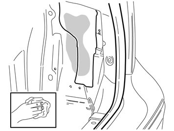
| | Grasp the upper edge of the right-hand side cushion. Pull the side cushion forward so that the clip on the reverse releases (A). Slide the side cushion upwards. Remove the screw at the rear edge of the panel at the front/top of the right-hand side panel (B). Pull the panel upwards so that the four clips on the inside release.
|
|  | | J8504585 |
|
| | Pull off the rubber strip at the rear of the opening for the right-hand rear door. Carefully pry off the lower panel on the C-post on the right-hand side. Pry the top edge using a weatherstrip tool. Pull in the C-post panel so that the two upper clips release. Then continue pulling down until the last two clips release.
|
|  | | J8504570 |
|
| | Fold out the load securing eyelets on the right-hand side panel. Insert a scriber with an angled tip into the holes in the top of the covers (1). Turn the scriber so that the tip engages the reverse of the covers. Pull the covers off. Remove the screws in the load securing eyelets. Remove the screw (2) at the front/top edge of the side panel. Pull off the side panel at the top so that the two clips at the rear/bottom of the side window and the clip at the bottom of the D-post release. If the car has a 12V socket in the side panel, disconnect the connector from this socket. Lift out the side panel.
|
|  | | J3904767 |
|
| | Applies to cars equipped with Parking Assistance Module (PAM) Remove the Parking Assistance Module (PAM) behind the right-hand rear wheel arch. Detach the surrounding cables if necessary.
|
|  | | J8504615 |
|
| | |
|  | | J8903538 |
|
|  | | J8903539 |
|
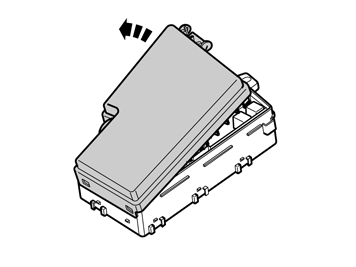
| | Illustration A applies to cars without RTI (road traffic information) Illustration B applies to cars with RTI (road traffic information) Remove the screws and the nuts holding the AM/FM tuner module (AFM) and the traffic message channel module (TMC) in the bodywork. Remove the AM/FM tuner module (AFM) and the traffic message channel module (TMC) from the bodywork. Disconnect the wiring if necessary. Place the AM/FM tuner module (AFM) and the traffic message channel module (TMC) to one side.
|
| | |
|  | | IMG-271588 |
|
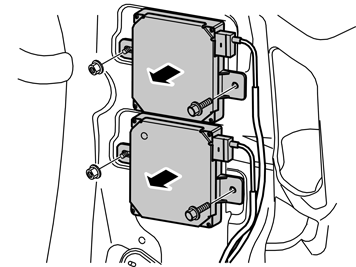
| | Installing the control module |
| | | IMG-226726 |
|
| | |
| | | IMG-222283 |
|
| | |
| | | IMG-222282 |
|
| | |
| | | IMG-271592 |
|
| | |
| | | IMG-271591 |
|
| | |
| | | IMG-271590 |
|
| | |
|  | | IMG-271589 |
|
| | Connect the connector from the wiring to the control module. Press the control module on the rear display screen in such a way that the wiring connector is not located at the edge of the lower edge of the display screen.
|
|  | | IMG-271593 |
|
| | | J3703684 |
|
| | Illustration A Look for the pre-routed 2–pin gray connector (1) for the control module power supply, and the pre-routed 5–pin green connector (2) for signals to the control module. The connectors are clamped at the front edge of the large hole in the side of the bodywork.
Note!
If the car is equipped with an Accessory Electronic Module (AEM) then the green connector is not clamped but hangs loose. |
Connect the connectors to the control module. Reinstall the AM/FM tuner module (AFM) / traffic message channel module (TMC).
Illustration B Applies to cars from CH 40000-, with Parking Assistance Module (PAM) Detach the green (GN) five pin connector (1) which is taped at the Parking Assistance Module (PAM) cable's rubber grommet. Plug the green connector into the Trailer Module (TRM).
|
| | | IMG-269603 |
|
| | Applies to V50s manufactured after w720 Pull up the catch on the cover on the fuse box in the engine compartment. Pull up the cover and remove it.
|
| | | IMG-269623 |
|
| | Applies to V50s manufactured after w720 Take a 40 A fuse from the kit and install it in terminal 14 in the fuse holder. Reinstall the cover.
|
| | |
| | Finishing work Reinstall the insulation panel. Refit the Parking Assistance Module (PAM), if the car is equipped with one. Refit any other detached cables. Reinstall the side panel. If the car has a 12V socket, connect the connector to this. Tighten the screws for the load securing eyelets. Tighten to 24 Nm (18 lbf.ft.). Reinstall the panel at the front/top of the side panel. Press downwards so that the catches engage. Tighten using the screw. Reinstall the C-post panel. Reinstall the side bolster. Reinstall the rubber strip in the door opening. Fold the backrest and seat back into place. Reinstall the rubber strip in the tailgate opening. Reinstall the sill trim panel in the tailgate opening. Reinstall the cargo compartment carpet. Program the software.
|