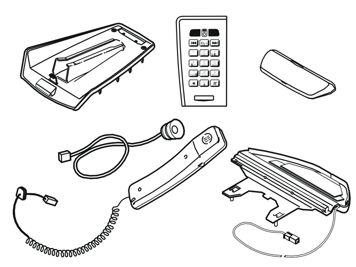
| | |
|  | | A8800136 |
|
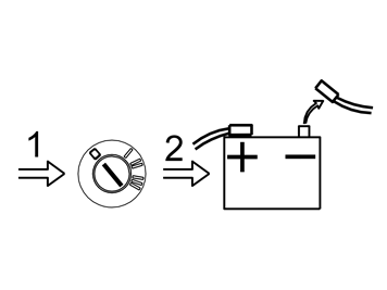
| | Preparations Note the anti-theft radio code (if applicable) Move the front seats to their rearmost, uppermost positions Turn the ignition key to position 0 Remove the key from the ignition switch (does not apply to cars with automatic gearboxes) Disconnect the battery negative lead.
Note!
Wait at least five minutes before disconnecting the connectors or removing other electrical equipment. |
|
|  | | M8502988 |
|
| | |
|  | | M8502991 |
|
| | |
|  | | M8503027 |
|
| | |
|  | | M8503705 |
|
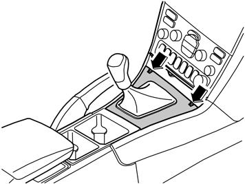
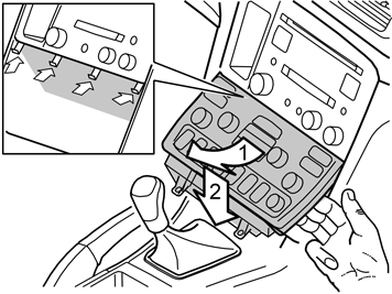
| | Angle the dashboard environment panel outwards so that it is possible to insert a couple of fingers between the centre console and the
rear of the dashboard environment panel Remove the dashboard environment panel. Pull it downward, maintaining the same angle. Some force is required because the panel is tightly
installed. It may be easier to pull one side loose at a time Disconnect the connectors on the reverse of the dashboard environment panel. Put the dashboard environment panel to one side.
Note!
If any of the outer hooks break off, these must be repaired. The method for this can be found in the Workshop Manual in the section about
the dashboard. |
|
|  | | M3903036 |
|
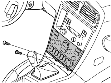
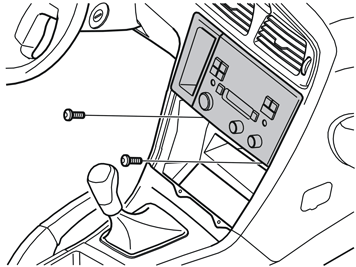
| | Remove the screws (1) from the radio bracket Pull out the bracket with the radio. Pull the lower corner while pressing downwards Disconnect the connectors on the radio. Place the bracket and the radio to one side.
|
|  | | M8503133 |
|
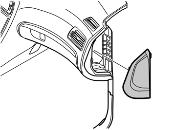
| | Remove the right and left-hand side centre console panels (1). Turn the clip at the rear edge of the panel through 90°. Pull the
rear edge of the panel outwards and backwards Remove the two screws on the panel (2) under the glove compartment. Remove the panel. Then pull the panel downwards / backwards at the
rear edge, it is secured by three clips Remove the sill moulding (3) on the right-hand side. Pull the front edge of the sill moulding back to release it. Then pull the moulding
upwards.
|
|  | | M8502816 |
|
| | |
| | Installing the microphone in the rear view mirror |
|  | | D8802007 |
|
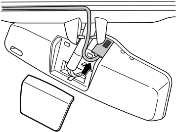
| | Installing the microphone in the rear view mirror |
|  | | M8803121 |
|
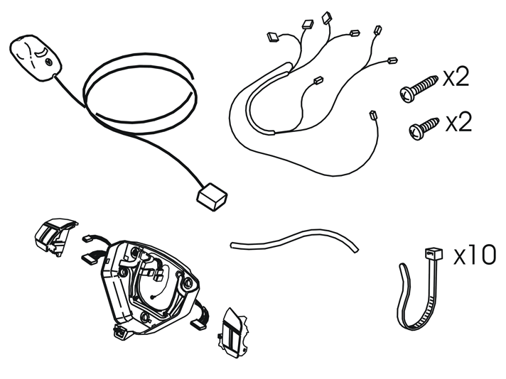
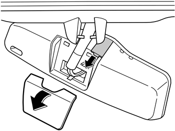
| | Install the new microphone (from the kit) in the rear view mirror Install the cable from the microphone between the window and the headlining. Use butyl tape. Route the cable towards the left-hand
A-post.
|
|  | | M3703230 |
|
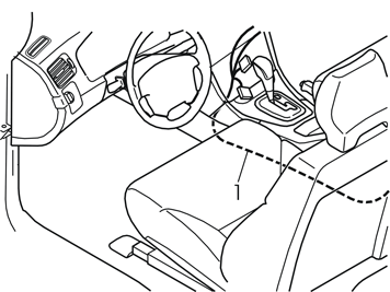
| | Take the cable harness from the kit. Position the cable harness in the radio compartment Route the cable to the handset (1), from the centre console down along the air ducts Continue to route the cable along the centre console, under the carpet, up through the carpet and into the rear end of the centre
console.
|
| | |
|  | | D3500908 |
|
| | |
|  | | D3500909 |
|
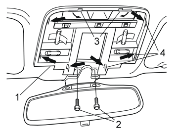
| | Remove the bracket (1) and mirror. First remove the screws (2) and bend the tabs (3) forward Detach the clips (4) by pressing the clips inwards. Detach one side at a time Pull the bracket downwards so that it releases from the mountings. Allow the bracket to hang loosely from the wiring.
|
|  | | D3500910 |
|
| | |
|  | | D3902236 |
|
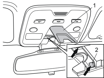
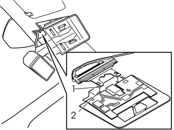
| | Install the new antenna. Carefully bend the headlining downward and slide the antenna backward and inwards. Align the antenna lugs (1)
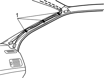
with the grooves in the bracket (2) Insert the cable at the inside of the front edge of the headlining. Route the cable out towards the right-hand A-post Secure the cable using butyl tape.
|
|  | | M8503136 |
|
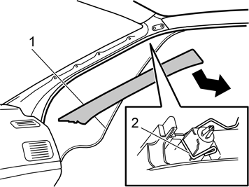
| | Remove the rubber strip (1) at the front edge of the front door on the right hand side Remove the A-post panel. Pull out the upper edge of the panel to release the two clips Remove the spring (2) from the upper clip holder Pull the panel straight up/back.
|
|  | | M8504683 |
|
| | |
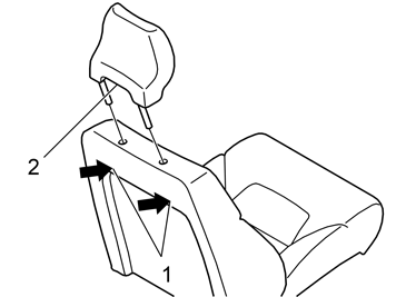
| | Installing the loudspeakers in the head restraint |
|  | | D8502423 |
|
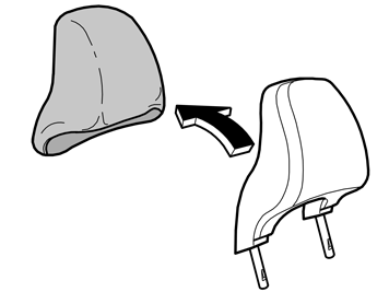
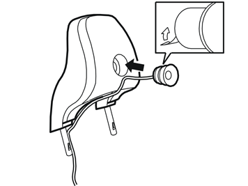
| | Installing the loudspeakers in the head restraint |
|  | | A3601074 |
|
| | |
|  | | D3902380 |
|
| | Remove the backing from the double-sided adhesive tape on the reverse of the loudspeaker. Secure the loudspeaker in the cut out on the
head restraint Route the cable down into the existing channel in the head restraint. Continue along the support leg Tape the cable in the channel on the head restraint Reinstall the upholstery on the head restraint.
|
|  | | A3602182 |
|
| | Close the zip fastener. Zip fastener missing: use a suitable zip fastener catch from the kit Secure the ends using staples Push the ends of the zip fastener inside the upholstery.
|
|  | | D3701684 |
|
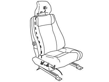
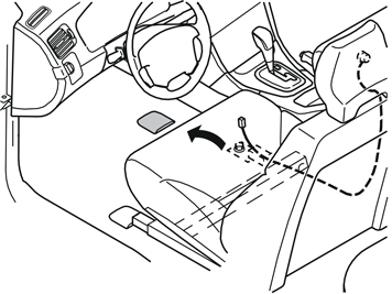
| | Route the cable down inside the upholstery and down under the seat. Use a piece of wire or something similar Position the connector at the front edge of the seat Reinstall the head restraint Secure the cable onto the member under the seat using tie straps.
|
|  | | M3702210 |
|
| | |
|  | | M3703217 |
|
| | Route the cable (1) from the centre console, along the air ducts and forward to the cable (2) from the loudspeaker in the head restraint
Connect both connectors to each other. Secure the connectors for the SIPS pipe under the front edge of the seat Adjust the length of the cables so that the seat moves freely between its end positions without stretching the cables Hide the excess cable under the carpet Reinstall the cover for the seat mounting.
|
| | |
|  | | M3702212 |
|
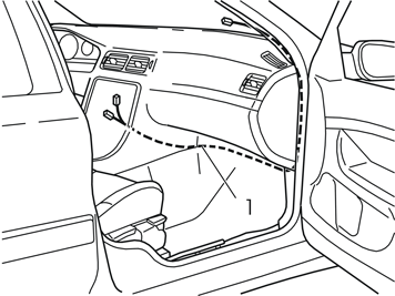
| | Cable routing Route the cable harness (1) to the antenna and the microphone down along the right-hand side of the centre console, along the air ducts
Continue to route the cable harness inside the carpet on the right hand side of the centre console and via the inside of the front edge
of the carpet. Route the cable harness along the right end of the dashboard and up to the previously routed connectors from the antenna and
microphone Connect the relevant connector to the antenna and microphone. Wrap foam tape around them and clamp securely Reinstall the A-post panel. Reinstall the panel on the right-hand end of the dashboard Reinstall the rubber strip in the door opening Reinstall the sill panel Reinstall the panel under the glove compartment.
|
| | |
|  | | M8503589 |
|
| | |
|  | | M8503590 |
|
| | |
|  | | M8503588 |
|
| | |
|  | | M8503599 |
|
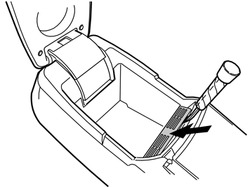
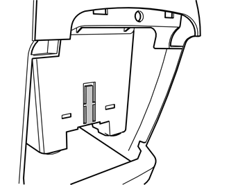
| | Insert a small screwdriver between the centre console locker hinges and the centre console Press in the two catches on the inside. At the same time pull the rear end backwards until it releases Position the rear end at the rear edge of the centre console. Do not disconnect the connectors.
|
|  | | M8503591 |
|
| | |
|  | | M8503797 |
|
| | Remove the two screws. Remove the panel from the inside of the centre console locker cover. Place the cover to one side. It will not be
reused Hook the front edge of the new handset holder on the inside of the centre console locker cover Tighten the handset using the two screws.
|
|  | | M3702399 |
|
| | Install the new carphone handset in the holder Insert the carphone cable and the rubber bushing (1) in the bottom of the centre console locker. Install the rubber seal in the hole in
the rear end of the centre console locker so that the cable is pointing upwards Connect the carphone cable (2) with the previously pre routed cable (3) from the centre console Insert the rubber bushing into the hole as far as possible.
|
|  | | M3702400 |
|
| | Press the connector (1) for the carphone handset into the existing clamp on the inside of the rear end of the centre console Reinstall the rear end of the centre console. Press the rear end by the top edge. Ensure that the no cables are trapped Secure the front and rear edges of the centre console using the four screws.
Reinstall: the centre console locker bottom the panel in the front edge of the centre console locker both the centre console panels.
|
| | Installing the keypad in the centre console |
|  | | M3903057 |
|
| | Installing the keypad in the centre console Remove the old aluminium bracket from the radio. Remove the five screws Install the new aluminium bracket (1) (from the kit). Screw into place using the five screws (2) Press the new keypad (3) onto the frame. Ensure that the keypad locks securely into both the radio and the frame.
|
|  | | M3903338 |
|
| | Connect: the green connector (1) from the new cable harness for the radio the previously disconnected green (GN) connector (2) from the radio to the green (GN) connector (3) in the new cable harness the connectors (4, 5) in the new cable harness to the keypad (6) the existing connectors (previously disconnected) to the radio.
|
|  | | M3903059 |
|
| | Insert the aluminium frame with the radio and keypad (1) almost all the way into the centre console. Angle and lift up the frame so that
the upper guide is in the correct position. Then insert the lower section of the frame so that it rests in the fixed position. Tighten using the
screws (2) Connect the dashboard environment panel connectors Reinstall the dashboard environment panel (3). Angle and lift up the panel so that the upper guide is in the correct position. Then
insert the lower section of the panel so that it rests in the fixed position Tighten the dashboard environment panel using the screw (4). Tighten to 3 Nm (2 lbf.ft.) Press the gear selector lever panel into place Reinstall the panel in front of the gear selector lever.
|
| | Installing the keypad in the steering wheel |
|  | | M6400668 |
|
| | Installing the keypad in the steering wheel |
|  | | M6400670 |
|
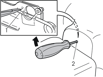
| | Insert a screwdriver in the hole on the rear edge of the steering wheel, at right angles to the rear surface of the steering wheel
Insert a screwdriver as far as possible to determine the position of the end of the spring clip (1) Position the end of the screwdriver on top of the spring clip Pry the screwdriver upwards towards the upper edge of the hole (2) until the spring releases and one side of the steering wheel module
springs out and releases from the mounting Turn the steering wheel 180°. Carry out the procedure on the other side Turn the steering wheel to the neutral position.
|
|  | | M3903271 |
|
| | |
|  | | M6400671 |
|
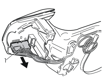
| | Remove: the screw (1). Remove the ground lead the connector (2) for the horn and the keypads the three screws (3). Lift out the horn (4).
|
|  | | M3702378 |
|
| | Applies to cars with pre-routed wiring |
|  | | M3903276 |
|
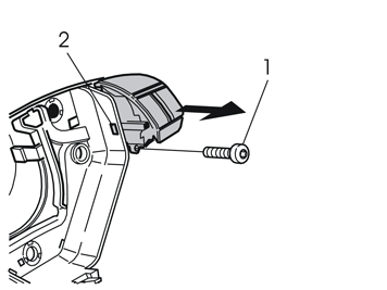
| | Remove the screw (1) in the dummy button on the right hand side of the horn -Press in the catch (2). At the same time pull the dummy button from its socket. Place to one side If there is pre-routed wiring and connectors, continue to point 45 If there is no existing wiring and connectors the horn must be replaced. There is a new one in the kit. Continue with points 43 and 44.
|
|  | | M3903278 |
|
| | Applies to cars without existing wiring Remove the screw (1) in the dummy button on the left-hand side of the horn Press in the catch (2). At the same time pull the dummy button from its socket.
Note!
Take care of the dummy button, it will be reused. |
Place the old horn to one side. The horn will not be reused.
|
|  | | M3903304 |
|
| | Applies to cars without existing wiring Take the new horn from the kit Insert the new left dummy button in its socket on the new horn Press the dummy button until the catch engages Install the screw. Tighten the dummy button Connect the connector to the dummy button.
|
|  | | M3903280 |
|
| | Take the remote control keypad and insert it in its socket Press the keypad until the catch engages Install the screw. Tighten the keypad Connect the connector to the keypad.
|
| | Reinstall the horn. According to point 40 in reverse order. Ensure that the three springs are correctly positioned. Check that the ground
lead is not trapped Tighten the screws crosswise. Tighten to 6.5 Nm (5 lbf ft.) Reinstall the ground lead. Tighten the ground lead Connect the connector for the horn and the keypads Check the function of the horn. Press the horn all the way around its circumference.
|
|  | | M6400669 |
|
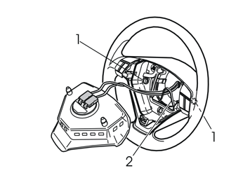
| | Insert the two lugs on the reverse of the steering wheel module in the two springs. Ensure that the sender wiring is unimpeded Press the steering wheel module into the mountings. Two clicks should be heard.
|
| | |
|  | | A8800137 |
|
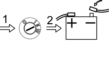
| | Finishing work Turn the ignition key to position II Reconnect the battery negative lead Program the software according to the service information in VIDA.
|

