|  | | IMG-344341 |
|
| | |
|  | | IMG-344142 |
|
| | |
|  | | IMG-344141 |
|
| | |
| | | IMG-344142 |
|
| | |
|  | | IMG-352732 |
|
| | |
|  | | IMG-352796 |
|
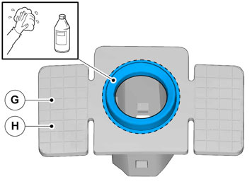
| | Note!
Also read the instructions on the spray can. |
|
|  | | IMG-344251 |
|
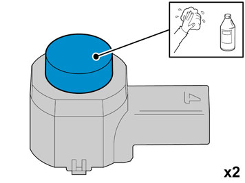
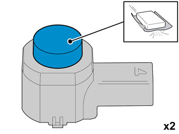
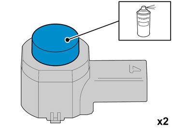
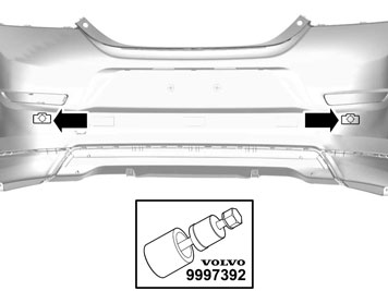
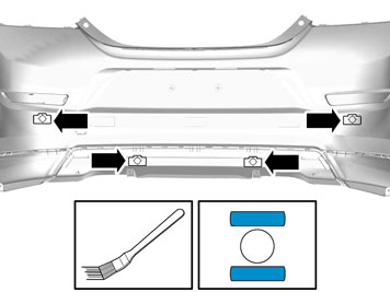
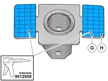
| | Caution!
protect the connections' contact surface against paint. |
Paint the sensors in the same colour code as the vehicle. use Volvo Touch-up paint. (Only use base coat.) Use: Volvo 2-K Varnish. P/N: 31335447.
Note!
Also read the instructions on the spray can. |
|
| | | IMG-352796 |
|
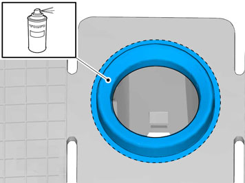
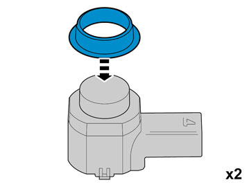
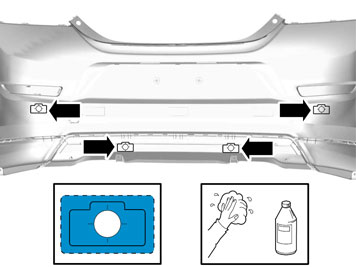
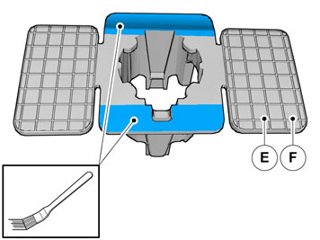
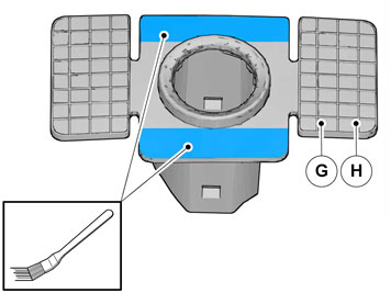
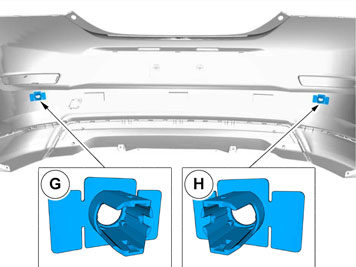
| | Paint the holders in the same colour code as the vehicle. Use Volvo Touch-up paint (Only use base coat.) Use: Volvo 2-K Varnish. P/N: 31335447.
Note!
Also read the instructions on the spray can. |
|
|  | | IMG-333934 |
|
| | Caution!
The paint must have dried after the first application. |
|
|  | | IMG-333935 |
|
| | |
|  | | IMG-333937 |
|
| | |
|  | | IMG-333940 |
|
| | |
|  | | IMG-333941 |
|
| | |
|  | | IMG-333942 |
|
| | |
|  | | IMG-333943 |
|
| | |
|  | | IMG-333944 |
|
| | |
|  | | IMG-333945 |
|
| | |
|  | | IMG-333946 |
|
| | |
|  | | IMG-333947 |
|
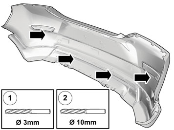
| | Ø 3 mm (7/64") Ø 10 mm (25/64")
|
|  | | IMG-333949 |
|
| | |
|  | | IMG-333950 |
|
| | |
|  | | IMG-333951 |
|
| | |
|  | | IMG-333953 |
|
| | |
|  | | IMG-333956 |
|
| | |
|  | | IMG-333955 |
|
| | |
|  | | IMG-333957 |
|
| | |
|  | | IMG-333958 |
|
| | |
|  | | IMG-250925 |
|
| | |
|  | | IMG-250926 |
|
| | Fold the central arm rest forward. Remove the central arm rest by grasping each end and pulling upwards until it releases at the rear edge from the backrest's lugs (1). Then pull forwards until the holders (2) on the sides of the backrest have slid out of the corresponding cut-out (3) in the central arm rest.
|
|  | | IMG-250927 |
|
| | |
|  | | IMG-250928 |
|
| | |
|  | | IMG-250929 |
|
| | |
|  | | IMG-250930 |
|
| | |
|  | | IMG-251368 |
|
| | |
|  | | IMG-251369 |
|
| | Unhook the safety clip from the panel. Angle out the panel at the lower edge, and then unhook it at the upper edge so that the upper clip releases.
|
|  | | IMG-251370 |
|
| | Remove the screw from the right-hand panel in the rear seat. Carefully pull off the panel from the body side. It is secured by 11 clips on the inside. Unhook it from the sill at the front edge.
|
|  | | IMG-240957 |
|
| | Lift up the floor hatch at the rear edge. Pull it backwards so that it detaches at the front edge. Turn the cover and lift out.
|
|  | | IMG-241183 |
|
| | |
|  | | IMG-253759 |
|
| | Remove the clips at the rear edge of the right-hand rear side panel. Carefully pull the side panel off, starting at the front edge/upper edge and then straight back until all clips at the top edge have released. Fold the panel inwards. Release it from the anchorage eyelets and lift it out of the load floor support.
|
|  | | IMG-241184 |
|
| | |
|  | | IMG-241200 |
|
| | |
|  | | IMG-333959 |
|
| |
Note!
Prepare and install one cradle at a time. |
|
|  | | IMG-333961 |
|
| | |
|  | | IMG-333962 |
|
| | |
|  | | IMG-333963 |
|
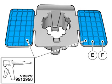
| | Apply a thin layer and even layer of adhesive.
Caution!
The adhesive must not come into contact with the tape. |
Use special tool P/N 9512767 Adhesive gun Use P/N 116173 Mixing pipe Use P/N 9511027 Adhesive
|
|  | | IMG-333964 |
|
| | |
|  | | IMG-335116 |
|
| | |
|  | | IMG-335118 |
|
| | |
|  | | IMG-335119 |
|
| | |
|  | | IMG-333960 |
|
| | |
|  | | IMG-333965 |
|
| | |
|  | | IMG-333967 |
|
| | Apply a thin layer and even layer of adhesive.
Caution!
The adhesive must not come into contact with the tape. |
Use special tool P/N 9512767 Adhesive gun Use P/N 116173 Mixing pipe Use P/N 9511027 Adhesive
|
|  | | IMG-333968 |
|
| | |
|  | | IMG-333969 |
|
| | |
|  | | IMG-333970 |
|
| | Press the holder towards the casing, but only at the places where there is tape. Repeat the method steps on the other cradle.
|
|  | | IMG-333971 |
|
| | |
|  | | IMG-333972 |
|
| | |
|  | | IMG-333973 |
|
| | |
|  | | IMG-254275 |
|
| | Note!
Vehicles with towbar wiring, see points for "Applies to vehicles with towbar wiring". |
|
|  | | IMG-254276 |
|
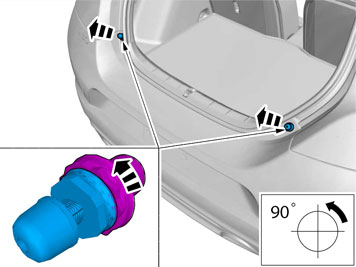
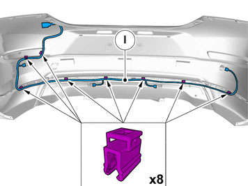
| | Take the cable harness with the rubber grommet from the kit. Pull the cable harness through the hole in the cargo compartment. Place the rubber grommet in position. Press the connector on the plastic bracket.
|
|  | | IMG-254277 |
|
| | |
|  | | IMG-254278 |
|
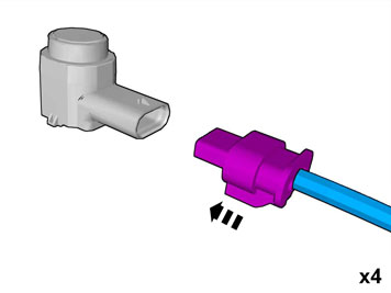
| | Note!
Ensure that the connector's catches click and are properly secured. |
|
|  | | IMG-254279 |
|
| | |
|  | | IMG-254280 |
|
| | |
|  | | IMG-254281 |
|
| | |
|  | | IMG-254282 |
|
| | |
|  | | IMG-222068 |
|
| | Applies to vehicles with tow bar wiring. Detach the towbar wiring connector from the Trailer Module (TRM). Release the terminal locking by pressing the catch down and pulling the locking straight out.
|
|  | | IMG-254283 |
|
| | Applies to vehicles with tow bar wiring. Disconnect all terminals from the connector.
Note!
Note the location of the cables in the connector. |
Use special tool P/N 9512810 or P/N 9512632. Insert the tool in the connector and release the locking. Pull out the cable with terminal. Pull out the cable harness through the rubber grommet. Remove the rubber grommet, it shall not be re-used.
|
|  | | IMG-254284 |
|
| | Applies to vehicles with tow bar wiring. Cut off the free rubber spout (1) on the rubber grommet of the PAS wiring. Lubricate the tow hitch wiring using Volvo's low temperature grease and thread the tow bar wiring (2) through. Connect the terminals to the connector. Secure the locking and connect to the trailer module (TRM).
|
|  | | IMG-254285 |
|
| | Applies to vehicles with tow bar wiring. The existing 5 pin green connector is connected to the trailer module (TRM) (1). Disconnect the connector for the control module and connect it to the cable harness of parking assistance (2). Disconnect the 5 pin green connector (3) that is taped to the cable harness and connect it to the trailer module (TRM).
|
|  | | IMG-254286 |
|
| | Applies to all models Raise the bumper cover to the car. Connect the connectors for parking assistance and license plate lighting. Reinstall the bumper cover with its screws. Reinstall the stops for the tailgate.
|
|  | | IMG-254251 |
|
| | Reinstall in the cargo compartment: side panel clips for the cargo floor support sill molding sill trim panel applicable spare wheel jack and other parts in the cargo floor support the floor hatch
|
|  | | IMG-333974 |
|
| |
Note!
There are 10 clips on the reverse of the panel that must engage in the body. Take care when aligning so that the clips do not break. Broken clips must be replaced with new ones. |
|
|  | | IMG-251430 |
|
| | Reinstall the side panel by first aligning it on the sill at the front edge and then pressing it against the body side, ensure that all clips engage. Tighten the panel using existing screws.
|
|  | | IMG-251432 |
|
| | |
|  | | IMG-242268 |
|
| | |