| | |
|  | | IMG-242207 |
|
| | |
|  | | IMG-242208 |
|
| | |
|  | | IMG-242209 |
|
| | |
|  | | IMG-242210 |
|
| | |
|  | | IMG-242211 |
|
| | |
|  | | IMG-242212 |
|
| | |
|  | | IMG-242213 |
|
| | |
|  | | IMG-242214 |
|
| | |
|  | | IMG-242215 |
|
| | |
|  | | IMG-242216 |
|
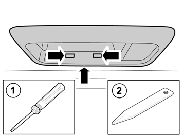
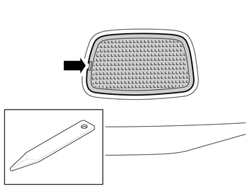
| | Remove the lamp. Unplug the connector.
|
|  | | IMG-242218 |
|
| | |
|  | | IMG-242219 |
|
| | |
|  | | IMG-242220 |
|
| | |
|  | | IMG-242221 |
|
| | |
|  | | IMG-242222 |
|
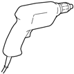
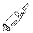
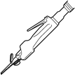
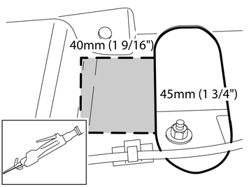
| | Applies to cars without vibration damper Mark out and saw out the hole as illustrated. Vacuum.
|
|  | | IMG-246926 |
|
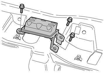
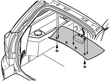
| | Applies to cars with vibration damper installed Remove the vibration damper by removing the three screws.
|
|  | | R8504201 |
|
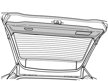
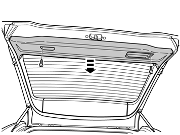
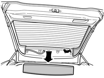
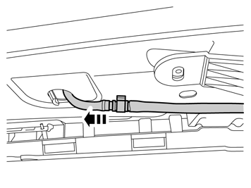
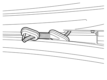
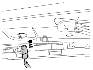
| | Remove the rear roof panel covers and the screws beneath them. Carefully pry off the panel at the rear edge. Use a plastic weatherstrip tool. Pull the rear edge of the panel downwards until the four clips on the top release. If the car is equipped with lighting in the panel, unplug the connector from the panel. Pull the panel backwards to release it.
|
|  | | IMG-242224 |
|
| | |
|  | | IMG-242225 |
|
| | |
|  | | IMG-242226 |
|
| | |
|  | | IMG-242227 |
|
| | |
|  | | IMG-242228 |
|
| | |
|  | | IMG-242230 |
|
| | |
|  | | IMG-242231 |
|
| | |
|  | | IMG-242232 |
|
| | |
|  | | IMG-242233 |
|
| | |
|  | | IMG-242234 |
|
| | |
|  | | IMG-242235 |
|
| | |
|  | | IMG-242236 |
|
| | |
|  | | IMG-242237 |
|
| | |
|  | | IMG-242238 |
|
| | |
|  | | IMG-242239 |
|
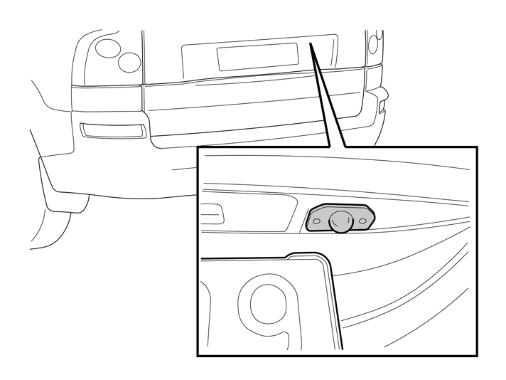
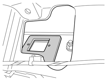
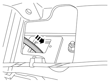
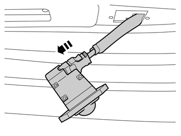
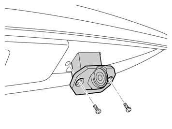
| | Screw the right-hand screw fully in the camera. Align the template so that the right-hand hole in the template is directly above the right-hand hole in the lid. Hold the template in position (inside the hole in the lid) and, at the same time, tighten the camera's right-hand screw so it holds. Align the left-hand holes with each other, fit the screw and tighten the camera.
|
| | Cargo compartment, preparations |
|  | | IMG-242240 |
|
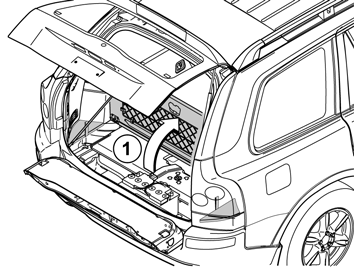
| | Cargo compartment, preparations Applies to cars with two rows of seats Fold up the floor hatch (1). If the floor hatch is equipped with a grocery bag holder, the holder is secured with a strap on both ends of the storage compartment. Detach the straps. Remove the storage compartment under the floor hatch. Remove the floor hatch by folding it almost completely closed and pulling it backwards from the mountings until it releases.
Applies to cars with three rows of seats and integrated carrier bag holder on the underside of the floor hatch Fold up the floor hatch (1). Detach the two straps on the panel under this. Lift up the rear edge of the panel, fold the floor hatch back towards the panel and lift out the floor hatch with the panel.
Applies to cars with three rows of seats without an integrated carrier bag holder Fold up the floor hatch (1) at the rear edge and lift it out.
|
|  | | R3100130 |
|
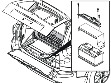
| | Slide the driver's seat fully forwards and then fully upwards from the rear edge. Remove the three screws in the battery holder. Lift the battery holder out. Remove the battery cover.
|
|  | | IMG-246024 |
|
| | |
|  | | IMG-242241 |
|
| | |
|  | | IMG-242242 |
|
| | |
| | |
|  | | R3903738 |
|
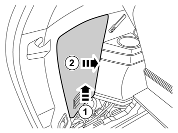
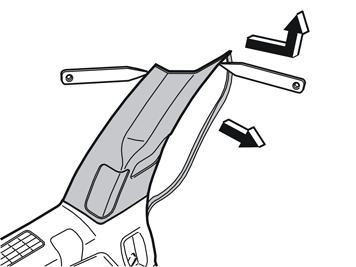
| | Pull off the rubber strip on the rear edge of the door opening for the left-hand rear door opposite the left C-post panel. Carefully pry off the left-hand C-post panel sides at the top. Use a plastic weatherstrip tool. Then pull until the three clips on the inside release. Do not damage the headlining or the panel. If a headphone socket is mounted, disconnect the connector to such. Remove the panel by pulling upwards slightly and unhooking it from the side panel.
|
|  | | R8504123 |
|
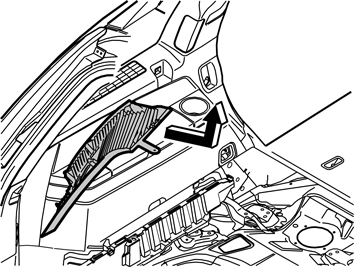
| | Carefully loosen the D-post panel. Start from the top and continue downwards until the three clips on the inside have released. Disconnect the connector on the D-post panel (if the car has a loudspeaker in the D-post, the connector is on the loudspeaker). Remove the panel by pulling upwards slightly and unhooking it from the side panel.
|
|  | | R8504313 |
|
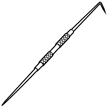
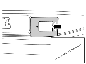
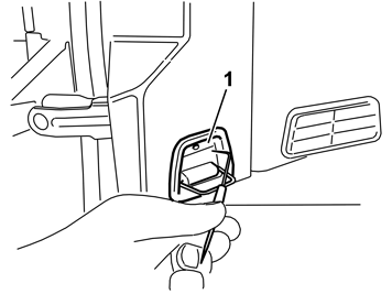
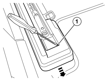
| | Fold out the load securing eyelet. Take a scriber or special tool part no.9995919 and insert the angled tip in the hole in the top edge of the cover. Twist the scriber so it grips the rear of the cover (1) and pull it loose. This should be carried out on both the front and rear load securing eyelets.
|
|  | | R8504315 |
|
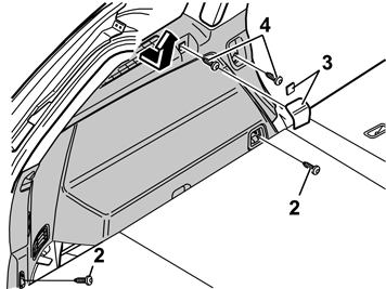
| | Applies to cars with two rows of seats Remove the screws (2) on the load securing eyelets. Remove the cover (3), by prying off using a weatherstrip tool or a small screw driver. Remove the screws (4). Remove the panel by pulling out the upper edge slightly so that the clips on the inside release. Pull the panel straight up.
|
|  | | R8504316 |
|
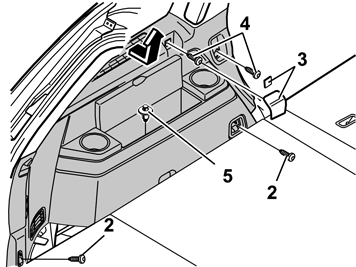
| | Fold up the left-hand seat in the third row of seats. Remove the screws (2) on the load securing eyelets. Remove the cover (3), by prying off using a weatherstrip tool or a small screw driver. Remove the screws (4). Remove the clip (5) in the bottom of the storage compartment. Remove the panel by pulling out the upper edge slightly so that the clips on the inside release. Pull the panel straight up.
|
|  | | IMG-242243 |
|
| | |
| | Preparations, passenger compartment |
|  | | IMG-242244 |
|
| | Preparations, passenger compartment |
|  | | IMG-242245 |
|
| | |
| 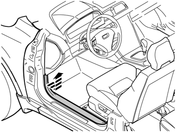 | | IMG-242246 |
|
| | |
| 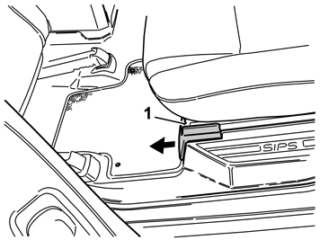 | | R8504309 |
|
| | |
| 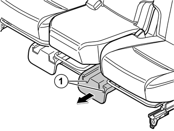 | | R8504310 |
|
| | |
|  | | IMG-242247 |
|
| | |
| 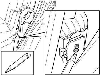 | | IMG-245600 |
|
| | |
|  | | IMG-242248 |
|
| | |
| | Steps 51-66 apply to cars with an accessory electronic module (AEM) installed |
|  | | R8504158 |
|
| | Steps 51-66 apply to cars with an accessory electronic module (AEM) installed Removal, cable harness |
|  | | IMG-273225 |
|
| | |
|  | | IMG-274168 |
|
| 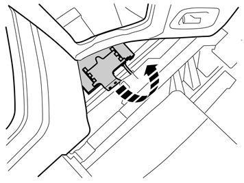 | | IMG-274169 |
|
| 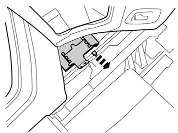 | | IMG-274170 |
|
| | Illustration A Illustration B Illustration C |
|  | | IMG-274171 |
|
| | |
|  | | R3703513 |
|
| | |
|  | | R3905101 |
|
| | |
|  | | D3703496 |
|
| | |
|  | | R3703512 |
|
| | |
|  | | M3904942 |
|
| | |
|  | | M3703366 |
|
| | |
|  | | R3703511 |
|
| | |
| | |
|  | | R3603578 |
|
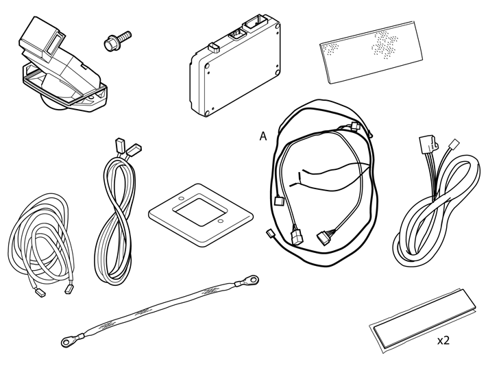
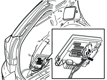
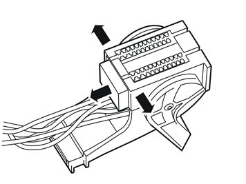
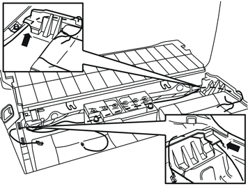
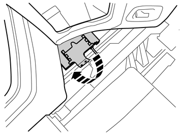
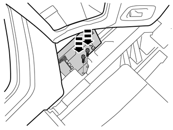
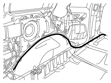
| | Installing the cable harness Take the new cable harness (purchased separately), marked A in the kit image and place it behind the battery. Pull the cable end with black 4-pin connector through the hole in the rear edge of the right-hand cargo floor support, up to the accessory electronic module (AEM). Route the other end in a corresponding way to the fuse holder on the left-hand side.
|
|  | | IMG-274224 |
|
|  | | IMG-274225 |
|
|  | | IMG-274226 |
|
| | Illustration A Illustration B Illustration C |
|  | | R3603579 |
|
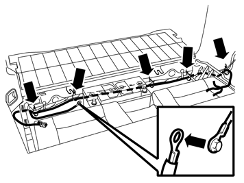
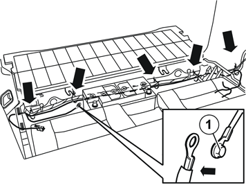
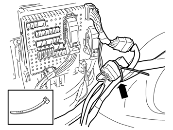
| | Take five cable ties from the kit and secure the wiring harness to the existing wiring harness as illustrated. Remove the ground screw and connect the ground lead (1) of the new wiring harness. Tighten the ground screw securely.
|
|  | | R3703512 |
|
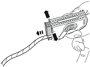
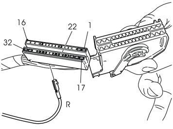
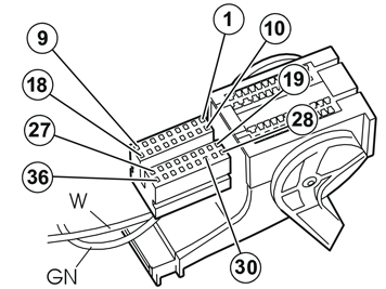
| | Connect the red (R) cable to terminal 22 in the brown connector which was disconnected from the fuse holder. Reinstall the connector in the holder Reinstall the connector in the fuse holder.
|
|  | | R3703511 |
|
| | Connect the green (GN) cable to terminal 19 in the gray connector that was disconnected from the fuse holder, and the white (W) to terminal 30.
Note!
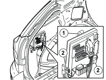
Make a note of the position number of the connector. The position numbers are located on the ends of the connector and in the bottom of the electronic control module. |
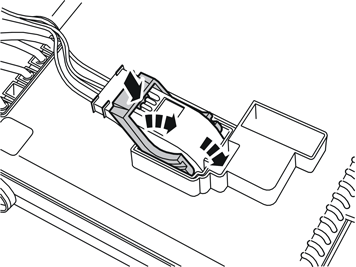
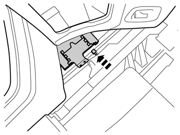
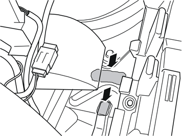
Reinstall the connector in the holder Reconnect the connector in the rear electronic control module (REM). Refit the Rear Electronic Module (REM).
|
| | Installation, parking assistance camera (PAC) |
|  | | R3603610 |
|
| | Installation, parking assistance camera (PAC) Steps 67-76 apply to cars without trailer module (TRM) |
|  | | R3603615 |
|
| | |
|  | | A0000335 |
|
| | |
|  | | IMG-242249 |
|
| | |
|  | | IMG-242250 |
|
| | |
|  | | R3603612 |
|
| | |
|  | | R3603616 |
|
| | |
|  | | IMG-242251 |
|
| | |
|  | | IMG-242252 |
|
| | |
|  | | IMG-242253 |
|
| | |
|  | | IMG-242254 |
|
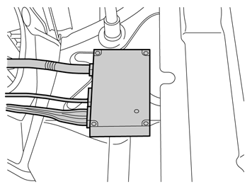
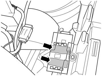
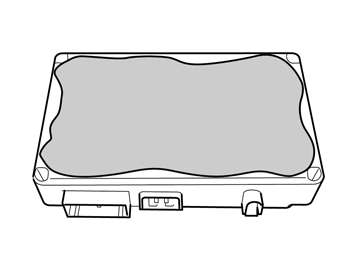
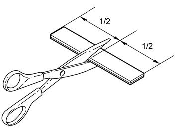
| | Steps 77-85 apply to cars with a trailer module (TRM) installed |
|  | | IMG-242255 |
|
| | |
|  | | IMG-222282 |
|
| | |
|  | | IMG-222283 |
|
| | |
|  | | IMG-222285 |
|
| | |
|  | | IMG-242256 |
|
| | |
|  | | IMG-242257 |
|
| | |
|  | | IMG-242258 |
|
| | |
|  | | IMG-242259 |
|
| | |
| | Connecting the rear electronic module (REM) |
|  | | IMG-242260 |
|
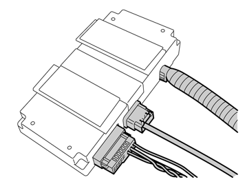
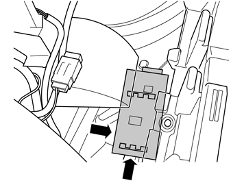
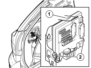
| | Connecting the rear electronic module (REM) Steps 86-89 apply to cars without an accessory electronic module (AEM) |
|  | | M3904942 |
|
| | |
|  | | M3703366 |
|
| | |
|  | | R3703511 |
|
| | Note!
Make a note of the position number of the connector. The position numbers are located on the ends of the connector and in the bottom of the electronic control module. |
Connect the green (GN) cable to terminal 19 in the connector. Connect the white (W) cable to terminal 30. Reinstall the connector in the holder Reconnect the connector in the rear electronic control module (REM). Refit the Rear Electronic Module (REM).
|
| | |
|  | | IMG-274233 |
|
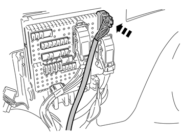
| | Steps 90-95 apply to cars with an accessory electronic module (AEM) installed Connect the large black female connector in the pre-routed cable harness, to the connector for towbar wiring in the fuse holder. Secure the excess of the large black male connector using a cable tie from the kit.
|
|  | | IMG-274234 |
|
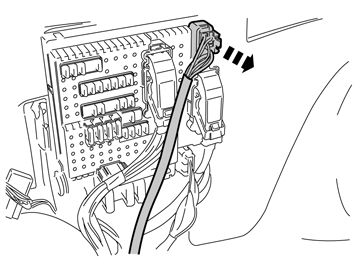
| | Steps 91-92 apply to cars with a towbar Disconnect the towbar wiring connector from the fuse holder.
|
|  | | IMG-274235 |
|
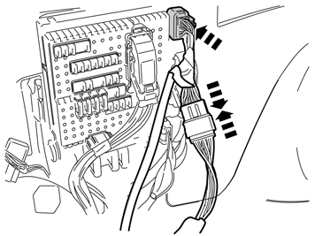
| | Connect the large black female connector in the pre-routed cable harness to the fuse holder. Connect the towbar wiring connector, which was disconnected from the fuse holder to the corresponding one in the routed cable harness.
|
|  | | IMG-274236 |
|
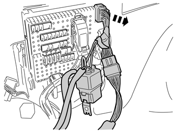
| | Steps 93-95 apply to cars with a towbar wiring adapter Disconnect the towbar wiring adapter's connector from the fuse holder.
|
|  | | IMG-274237 |
|
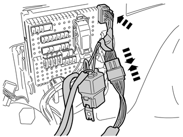
| | Connect the large black female connector in the pre-routed cable harness to the fuse holder. Connect the towbar wiring adapter's connector, which was disconnected from the fuse holder to the corresponding one in the routed cable harness.
|
|  | | IMG-274238 |
|
| | |
| | Connection to multimedia module (MMM) |
|  | | IMG-242261 |
|
| | Connection to multimedia module (MMM) |
|  | | IMG-242262 |
|
| | |
|  | | IMG-242263 |
|
| | |
|  | | IMG-242264 |
|
| | |
| | Installation, ground strip |
|  | | IMG-246927 |
|
| | Installation, ground strip |
|  | | IMG-246928 |
|
| | |
|  | | IMG-246929 |
|
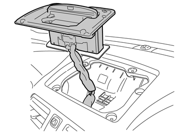
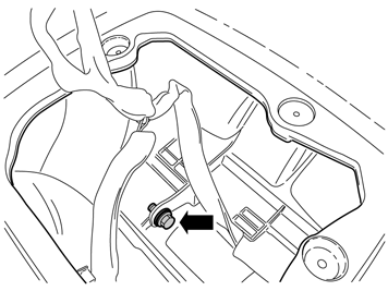
| | Applies to cars without a centrally mounted loudspeaker Lift up the monitor unit and place it on the dashboard.
Note!
Place some protection under the monitor unit so as not to damage the dashboard. |
Applies to cars with a centrally mounted loudspeaker Remove the three connectors.
|
|  | | IMG-246930 |
|
| | |
|  | | IMG-246933 |
|
| | |
|  | | IMG-246934 |
|
| | |
|  | | IMG-246935 |
|
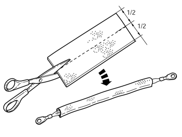
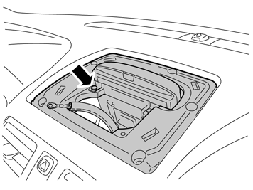
| | Applies to cars without a centrally mounted loudspeaker Refit the monitor unit and at the same time guide the earth braid up through the hole in front of the monitor. Remove the left-hand screw for the monitor.
|
|  | | IMG-246936 |
|
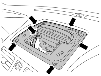
| | Applies to cars without a centrally mounted loudspeaker Place the earth braid over the hole where the screw was positioned, fit the screw and tighten the earth braid. Refit the five screws for the monitor unit. Refit the louvre.
|
|  | | IMG-248723 |
|
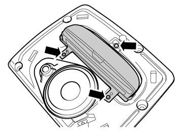
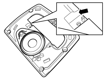
| | Steps 108-113 apply to cars with a centrally mounted loudspeaker Remove the three screws for the monitor. Remove the monitor by first angling it backwards at the lower edge and then guiding it out.
|
|  | | IMG-248724 |
|
| | |
|  | | IMG-248725 |
|
| | |
|  | | IMG-248726 |
|
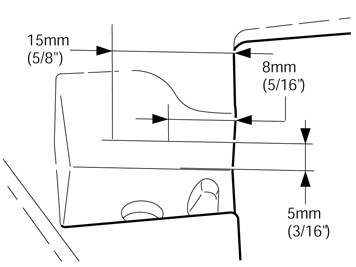
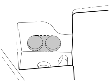
| | Pre-drill in the centers of the markings using a Ø 2mm (5/64") diameter drill bit. Then drill out the holes. Use a Ø 8mm " (5/16") drill bit. Cut away the part between the drill holes as illustrated.
|
|  | | IMG-248727 |
|
| | |
|  | | IMG-248728 |
|
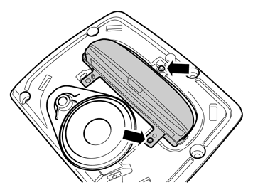
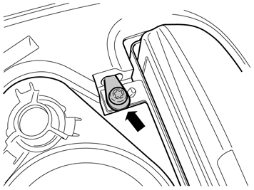
| | Take the loose end of the ground strip and thread it through the drilled holes from underneath. Secure the cable terminal using the screw for the monitor and tighten. Reinstall the monitor unit with its five screws. Refit the louvre.
|
| | |
|  | | IMG-336901 |
|
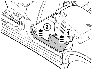
| | Finishing work Install: the sill trim panels. panel over the joint between the door sills. seat belt.
Note!
Check that the seat belt is secure by jerking it hard in an upwards direction. |
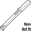
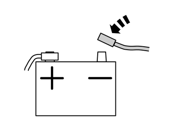
seat, tighten the screws to 50 Nm (36.8 lbf.ft.). seat links. side panels. Reconnect the battery negative lead
|
|  | | IMG-336904 |
|
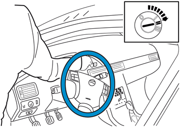
| | Warning!
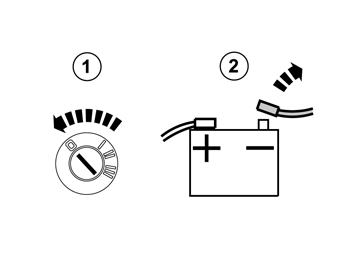
When the ignition is to be switched on for the first time after the battery has been disconnected, this must be done by standing outside the vehicle, stretching your arm in and avoiding the operating area for the airbags. |
|
|  | | IMG-242268 |
|
| | |
|  | | IMG-336903 |
|
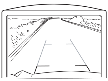
| | Perform a function test as follows Engage reverse gear Activate the screen for RTI Wait for the message "Update Environment" to appear on the screen Follow the on-screen instructions Switch off the ignition for at least 10 seconds. - Turn the ignition on Activate the screen for RTI Check that the support lines appear on the screen and that these react to steering wheel movements.
|
|  | | IMG-242268 |
|
| | |

