| | |
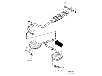
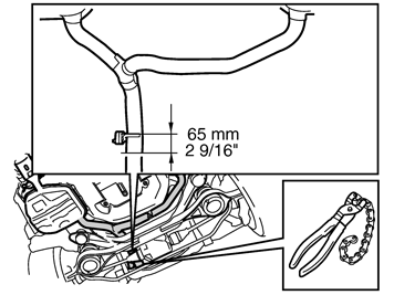
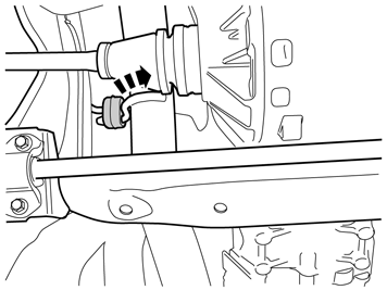
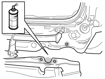
| | Applies to vehicles with twin rear silencers Note!
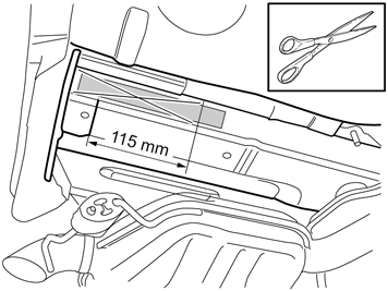
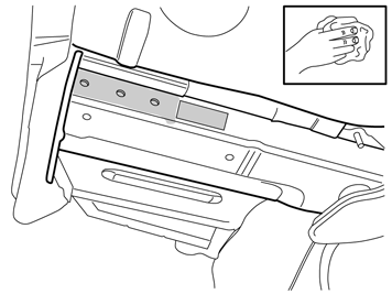
To facilitate access when tightening the towbar member, the exhaust system must be cut at the marking according to the instructions. It is important to use this method, otherwise there is a risk of damaging the exhaust system if the silencers are forced down for example. |
|
|  | | IMG-363036 |
|
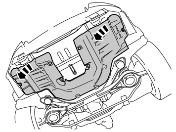
| | Note!
This colour chart displays (in colour print and electronic version) the importance of the different colours used in the images of the method steps. |
Used for focused part, the part that you are to do something with. Used as extra colors when you need to show or differentiate additional parts. Used for attachments that are to be removed/installed. May be screws, clips, connectors, etc. Used when the component is not fully removed from the vehicle but only hung to the side. Used for standard tools and special tools. Used as background color for vehicle components.
|
|  | | IMG-261524 |
|
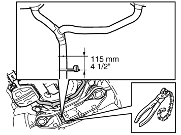
| | Note the engine version of the car. Enter VIDA under: Engine with mountings/ Intake and exhaust system/ Silencers and exhaust lines/ Silencer rear. Order exhaust clamp for joining the exhaust system.
|
| | |
|  | | IMG-259683 |
|
| | |
|  | | IMG-259753 |
|
| | |
|  | | IMG-259755 |
|
| | |
|  | | IMG-259754 |
|
| | |
|  | | IMG-379389 |
|
| | |
|  | | IMG-379404 |
|
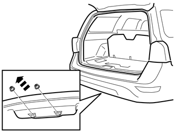
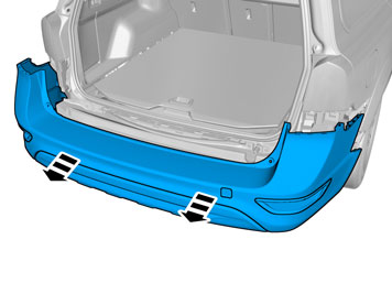
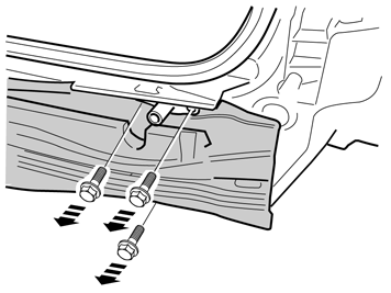
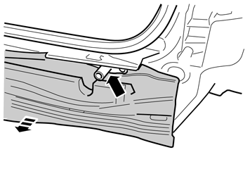
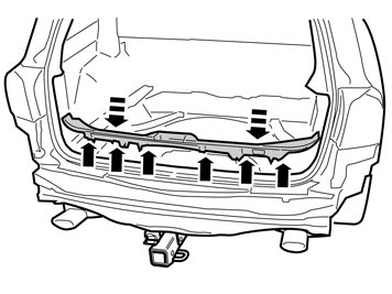
| | Caution!
Press the bumper casing down when removing, so as not to damage the rear lights. |
Note!
This step is easier with two people. |
|
|  | | IMG-379386 |
|
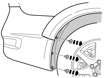
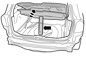
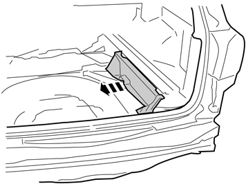
| | Note!
This step is easier with two people. |
|
|  | | IMG-379405 |
|
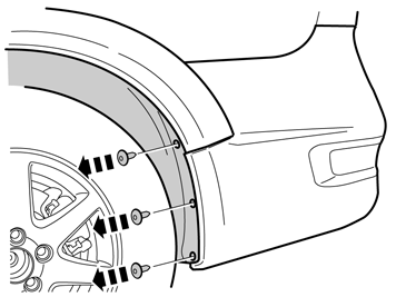
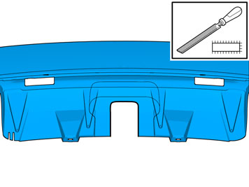
| | Caution!
Place the bumper cover on a suitable surface. |
Note!
This step is easier with two people. |
|
|  | | IMG-261414 |
|
| | |
|  | | IMG-259759 |
|
| | |
|  | | IMG-259760 |
|
| | |
|  | | IMG-259761 |
|
| | |
|  | | IMG-377019 |
|
| | |
|  | | IMG-377020 |
|
| | |
|  | | IMG-259763 |
|
| | |
| | |
|  | | IMG-260410 |
|
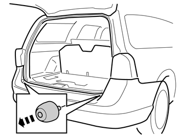
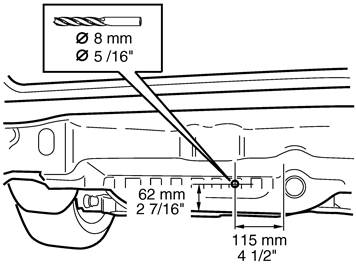
| | Accessory installation Applies to vehicles without spare wheel Note!
Check that there are no cable harnesses on the inside that obstruct the hole drilling process. |
Measure and make markings for making holes for the screw for the towing ball cradle. Pre-drill using a small drill bit. Drill out the hole to Ø 8 mm (5/16"). Deburr the edges of the hole, apply rustproofing agent and remove the drill swarf.
|
|  | | IMG-226142 |
|
| | |
|  | | IMG-226143 |
|
| | |
| | |
|  | | IMG-260845 |
|
| | Applies to vehicles with AWD |
|  | | IMG-260846 |
|
| | |
| | |
|  | | IMG-260847 |
|
| | Applies to vehicles with 2WD |
| | |
|  | | IMG-259825 |
|
| | Applies to all vehicles Hint
Get help from a colleague for this procedure. |
|
|  | | IMG-260849 |
|
| | |
|  | | IMG-260850 |
|
| | |
|  | | IMG-364281 |
|
| | |
|  | | IMG-260852 |
|
| | |
|  | | IMG-261098 |
|
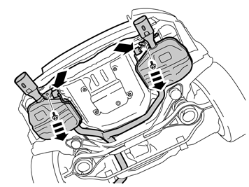
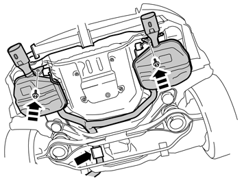
| | Check that the contact surfaces inside the side members are clean. If not, clean them opposite where the towing member's side plates shall be tightened. Take the towing member from the kit and insert the two side plates in the holes in the rear edge of the side members.
|
|  | | IMG-260853 |
|
| | |
|  | | IMG-261123 |
|
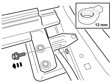
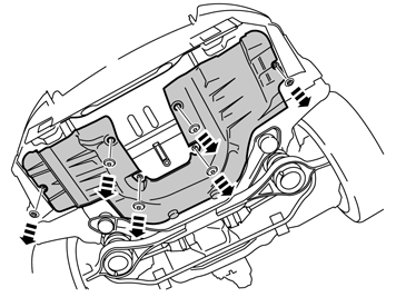
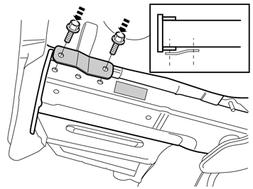
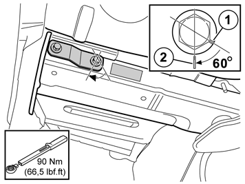
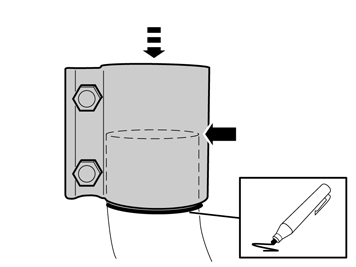
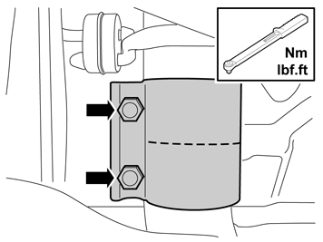
| | Torque tighten the screws to 90 Nm (66.5 lbf.ft.) and angle tighten to 60°. There may be occasions that a protractor cannot be used on the torque wrench when angle-tightening joints in confined spaces. Instead use a hex screw head to determine the angle. Make a mark on the screw head flange (1). Make another mark (2) in the side member or reinforcement bar. Now tighten the screw so that the screw head marking (1) lines up with the marking (2) on the side member/reinforcement bar. Repeat for all screws.
|
|  | | IMG-260855 |
|
| | |
|  | | IMG-261083 |
|
| | |
|  | | IMG-282943 |
|
| | |
|  | | IMG-282946 |
|
| | |
|  | | IMG-282963 |
|
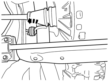
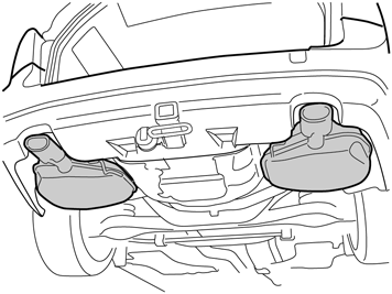
| | Request the assistance of a colleague, raise and reinstall the silencers with exhaust pipe in the exhaust clamp. Refit the mountings for the silencers. Torque tighten the screws to 50 Nm (37 lbf. ft.).
|
|  | | IMG-260865 |
|
| | |
|  | | IMG-282964 |
|
| | |
|  | | IMG-259875 |
|
| | |
|  | | IMG-259876 |
|
| | |
|  | | IMG-282983 |
|
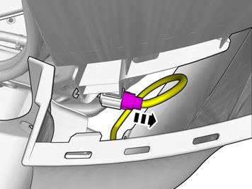
| | Note!
Do not damage the cable harness that is on the towing eyelet's inner screw. |
|
|  | | IMG-364322 |
|
| | |
|  | | IMG-261101 |
|
| | |
|  | | IMG-377452 |
|
| | |
|  | | IMG-377459 |
|
| | |
|  | | IMG-377460 |
|
| | |
|  | | IMG-377461 |
|
| | |
|  | | IMG-377462 |
|
| | |
|  | | IMG-377466 |
|
| | |
|  | | IMG-377464 |
|
| | |
|  | | IMG-377465 |
|
| | |
| | |
|  | | IMG-261125 |
|
| | Installation Note!
Request the assistance of a colleague when carrying out this procedure to prevent damaging the bumper cover. |
|
|  | | IMG-259891 |
|
| | |
|  | | IMG-259892 |
|
| | |
|  | | IMG-261127 |
|
| | |
|  | | IMG-259894 |
|
| | |
|  | | IMG-364326 |
|
| | |
|  | | J8903208 |
|
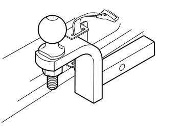
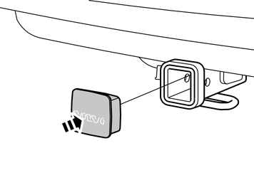
| | Remove the cover Take the ball holder, ball, washer, nut, lock bolt and locking pin from the kit. Insert the ball cradle in the towing member's square bracket until the holes in the ball holder and square bracket correspond. Slide the locking bolt into the hole. Lock the other side using the locking pin. Position the ball in the hole on the ball holder. Install the washer and nut. Torque tighten to 244 Nm (180 lbf.ft.).
|
| | |
|  | | IMG-228976 |
|
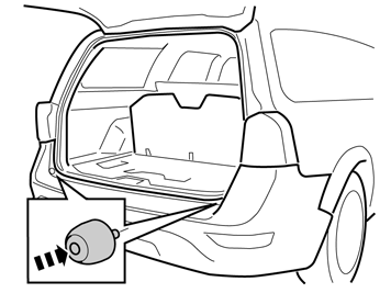
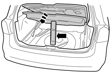
| | Applies to vehicles without spare wheel Remove the bag from the kit, put the towball inside and tie it up. Wind the long strap twice around the bag and tighten firmly.
|
|  | | IMG-231220 |
|
| | |
| | |
|  | | IMG-228980 |
|
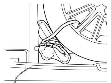
| | Applies to vehicles with spare wheel Remove the bag from the kit, put the towball inside and tie it up. Wind the long strap twice around the bag and once around the wheel and tighten firmly.
|
|  | | IMG-226150 |
|
| | |
|  | | IMG-261415 |
|
| | |
|  | | IMG-228982 |
|
| | |