|  | | IMG-297185 |
|
| | |
|  | | IMG-297204 |
|
| | |
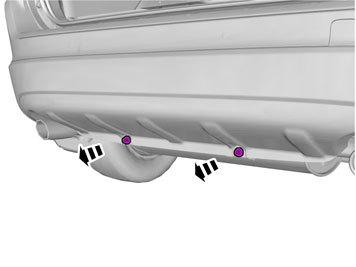
| | Applies to cars with skid plate |
|  | | IMG-284824 |
|
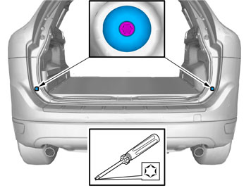
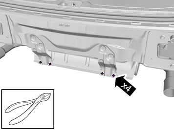
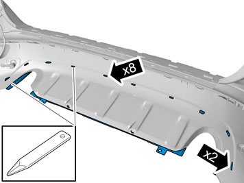
| | Applies to cars with skid plate Drill out the four rivets at the lower edge of the skid plate. Drill carefully so that the holes in the skid plate and bumper cover are not enlarged. Use a Ø 6 mm (15/64") drill bit. Remove any swarf and rivet residue.
|
|  | | IMG-285050 |
|
| | |
| | Applies to cars with R-design |
|  | | IMG-344779 |
|
| | Applies to cars with R-design |
| | |
|  | | IMG-297503 |
|
| | |
|  | | IMG-297504 |
|
| | Note!
Two persons should perform the following work. |
|
|  | | IMG-297523 |
|
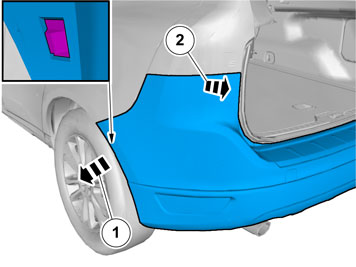
| | Note!
Two persons should perform the following work. |
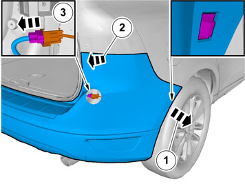
Carefully pull loose the bumper cover's end at the front edge on both sides. Carefully pull away the end of the bumper cover until the catches at the rear edge of the rear wing and under the tail lights release. Pull the bumper cover backwards to remove it.
Applies to cars with parking assistance. |
|  | | IMG-285056 |
|
| | |
| | Applies to older car models |
|  | | IMG-285062 |
|
| | Applies to older car models |
| | Applies to newer car models |
|  | | IMG-344780 |
|
| | Applies to newer car models Remove the pop rivets. Use: cutting pliers
|
| | |
|  | | IMG-291743 |
|
| | |
|  | | IMG-291744 |
|
| | |
|  | | IMG-285060 |
|
| | |
|  | | IMG-285061 |
|
| | |
|  | | IMG-285063 |
|
| | |
|  | | IMG-285064 |
|
| | |
|  | | IMG-285065 |
|
| | |
|  | | IMG-285066 |
|
| | |
|  | | IMG-285684 |
|
| | Check that the contact faces inside the side members are clean. If necessary, clean opposite where the towing member's side plates are to be fastened. Take the towing member from the kit and insert the two side plates in the holes at the rear edge of the side members.
|
|  | | IMG-285083 |
|
| | Take screws and the reinforcement bar from the kit. To maintain and adjust the position on the towing member two people should work together when the screws are entered into the weld nuts of the towing member.
Note!
Ensure that the reinforcement bar is positioned correctly, according to the image. |
Tighten the screws alternately on both sides.
|
|  | | IMG-285084 |
|
| | Tightening the screw joint Torque-tighten the screws to 140 Nm (103 lbf.ft.) and angle-tighten to 60°. When angle-tightening joints in tight spaces, a protractor applied to a torque wrench cannot be used. Instead, use a hex screw's head to determine the tightening angle. Use workshop liftpart no. 99985972 and fixture part no. 9995972 under the muffler to position it for easier access. Mark the screw head flange (1). Make a second mark (2) in the side member or reinforcement bar. Now tighten the screw so that the screw head marking (1) lines up with the marking (2) on the side member/reinforcement bar. Repeat for all screws.
|
|  | | IMG-285685 |
|
| | |
|  | | IMG-285686 |
|
| | |
|  | | IMG-285086 |
|
| | |
| | Applies to older car models |
|  | | IMG-285687 |
|
| | Applies to older car models Tighten the heat shield. |
| | Applies to newer car models |
|  | | IMG-344784 |
|
| | Applies to newer car models |
| | |
|  | | IMG-285688 |
|
| | |
|  | | IMG-285089 |
|
| | |
|  | | IMG-292283 |
|
| | |
|  | | IMG-285091 |
|
| | Apply high-viscosity anti-corrosion agent on the marked unpainted sheet metal surfaces on both sides of the impact member. Also apply on the marked unpainted sheet metal surfaces on both sides of the side members' trailing edges.
|
|  | | IMG-285689 |
|
| | |
| | Applies to cars with R-design |
|  | | IMG-344782 |
|
| | Applies to cars with R-design |
| | |
|  | | IMG-366597 |
|
| | |
|  | | IMG-366596 |
|
| | |
|  | | IMG-366135 |
|
| | |
|  | | IMG-366233 |
|
| | Note!
Do not damage the bumper cover's painted surface. |
Cut according to the markings. Saw out so that the raised edge on the inside that marks the cut-out remains. Remove the tape. Smooth off the sawn edges with a fine toothed file.
|
| | Applies to cars with skid plate |
|  | | IMG-366603 |
|
| | Applies to cars with skid plate |
|  | | IMG-366604 |
|
| | |
|  | | IMG-366138 |
|
| | |
|  | | IMG-366184 |
|
| | Note!
Do not damage the skidplate's painted surface. |
Cut according to the markings. Saw out so that the raised edge on the inside that marks the cut-out remains. Remove the tape. Smooth off the sawn edges with a fine toothed file.
|
| | Applies to cars with R-design |
|  | | IMG-345097 |
|
| | Applies to cars with R-design |
|  | | IMG-367633 |
|
| | Note!
Do not damage the skidplate's painted surface. |
Cut according to the markings. Saw out so that the raised edge on the inside that marks the cut-out remains. Remove the tape. Smooth off the sawn edges with a fine toothed file.
|
|  | | IMG-367636 |
|
| | |
|  | | IMG-367637 |
|
| | |
|  | | IMG-344817 |
|
| | |
| | |
| | |
|  | | IMG-285097 |
|
| | Note!
Two people should carry out the following procedure. |
|
|  | | IMG-285098 |
|
| | Note!
Two people should carry out the following procedure. |
|
|  | | IMG-285099 |
|
| | |
|  | | IMG-285100 |
|
| | |
|  | | IMG-345099 |
|
| | |
| | Applies to cars with skid plate |
|  | | IMG-285707 |
|
| | Applies to cars with skid plate |
|  | | IMG-292303 |
|
| | Hint
The mounting strip on the skid plate can be bent out slightly if it is difficult to hook onto the holder. |
|
|  | | IMG-285709 |
|
| | |
| | Applies to cars with R-design |
| | | IMG-344779 |
|
| | Applies to cars with R-design |
| | |
|  | | IMG-345100 |
|
| | |
|  | | IMG-366654 |
|
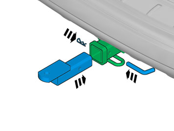
| | Take the ball retainer, lock bolt, and lock pin from the kit. Insert the ball holder in the towing member's square bracket until the holes in the ball holder and square bracket correspond. Slide the locking bolt into the hole. Lock the other side using the locking pin.
|
|  | | IMG-366655 |
|
| | Take ball, washer, and nut from the kit. Position the ball in the hole on the ball holder. Install washer and nut. Torque-tighten the screws with 224 Nm (180 lbf.ft.).
|
|  | | IMG-228982 |
|
| | |
|  | | IMG-285724 |
|
| | |
|  | | IMG-285723 |
|
| | |
|  | | IMG-290583 |
|
| | |
|  | | IMG-290584 |
|
| | |
|  | | IMG-285725 |
|
| | |
|  | | IMG-285726 |
|
| | |
|  | | IMG-285728 |
|
| | |