| | |
|  | | A8800136 |
|
| | |
|  | | IMG-251579 |
|
| | |
|  | | IMG-251580 |
|
|  | | IMG-304263 |
|
| | Illustration A applies to cars up to and including model year -2007 Illustration B applies to cars from and including model year 2008- |
|  | | IMG-251581 |
|
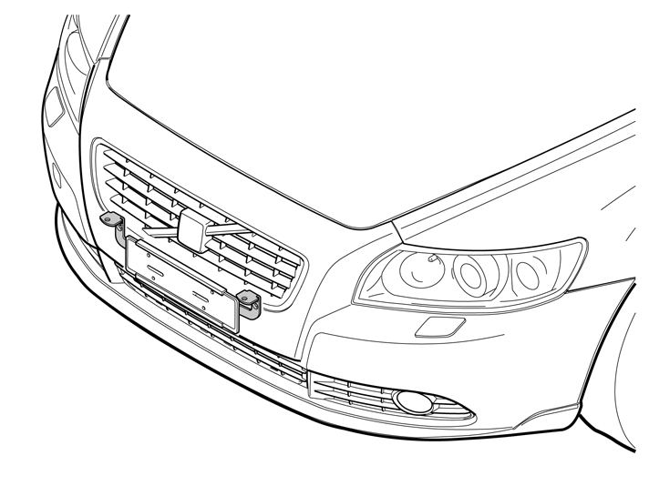
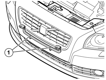
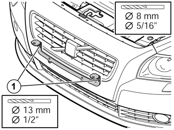
| | Pre-drill the two holes using a Ø 8 mm (5/16") drill bit in the centre of the brackets upper hole (1). Hold the drill straight and drill to the member inside. Remove the bracket for auxiliary lights. Drill out the holes using a Ø 13 mm (1/2") drill bit through the bumper cover and the expanded polystyrene layer to the member inside. Remove any swarf from the hole and smooth off the hole edges.
|
|  | | IMG-251582 |
|
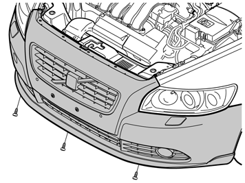
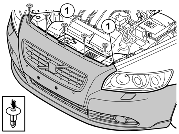
| | Removing the front bumper cover Remove the three screws securing the air baffle to the lower edge of the bumper cover.
|
|  | | IMG-251583 |
|
| | |
|  | | J8601109 |
|
| | |
|  | | J8601084 |
|
| | |
|  | | IMG-251584 |
|
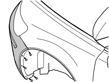
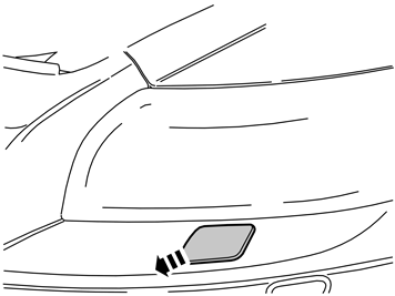
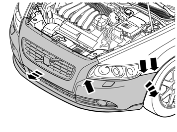
| | Detach the ends of the bumper cover on the left and right-hand sides. Grasp the end of the bumper cover inside the wing liner. Carefully pull the end of the bumper cover so that the five catches at the rear edge and under the lights release. Lift off the bumper cover Lift off the bumper cover. Disconnect the connectors for the fog lamps, if installed.
|
|  | | J8601184 |
|
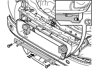
| | Remove the foam member by carefully pulling it straight out. Remove the screws (1) holding the horn completely and place them to one side. They will not be reused. Install the inner bracket and horn as illustrated and secure using the screws from the kit. Tighten to 10 Nm (7.5 lbf.ft.).
|
|  | | J8601185 |
|
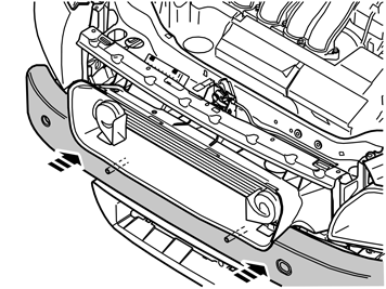
| | Reinstall the foam member and insert the corners of the bracket in the pre-drilled holes. secure the foam member in the applicable holes in the bumper rail inside. If it is a tight fit, the holes can be drilled out slightly to facilitate access.
|
|  | | J8601186 |
|
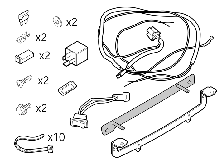
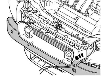
| | Take the cable harness for the auxiliary lights. Cut off the plastic clip that holds the two loose separate cable harnesses. Insert the cable for the auxiliary lights from the engine compartment and out along the grille. Measure with the cable so that you pull out the required length. Raise the bumper cover towards the car and hold it away from the car slightly. Pull out the end of the cable for the auxiliary lights through the other hole, seen from the right.
|
|  | | IMG-251585 |
|
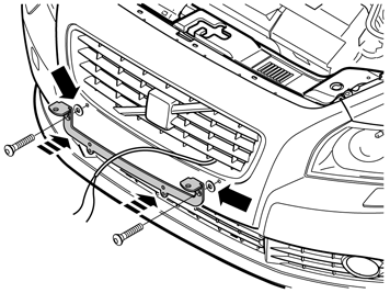
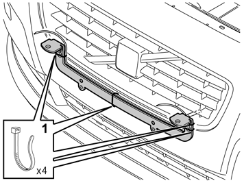
| | Reinstall the bumper by following the instructions in steps 5-9 in reverse order. Route the cable through the other hole from the right in the grille. Secure the bracket in the inner bracket's protruding horn with the screws and the washers from the kit but do not tighten them too hard yet. The washers must be between the horn and bracket.
|
|  | | IMG-251586 |
|
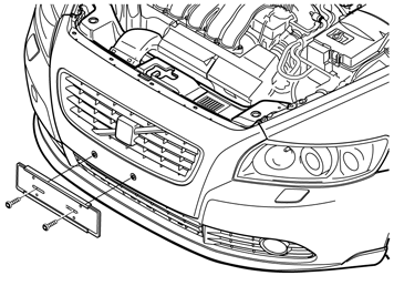
| | Pull the longer of the two cable ends to the right-hand mounting of the auxiliary lights bracket. Position the cable harness at the upper edge of the auxiliary lights bracket and secure by it using four cable ties (1) from the kit. Check that the screws for the number plate cradle are opposite the holes. Tighten the M8 screws. Tighten to 18Nm (13.3 lbf.ft.). Install the number plate cradle and tighten the screws.
|
| | Connecting auxiliary lights The kit contains flat pin connectors and plastic isolators that must be used to isolate the + cable.
Caution!
Read through the supplied installation instructions for your auxiliary lights. In most cases the wiring must be routed into the light housing, through a rubber grommet, before securing the flat pin connectors. |
|
|  | | J3703352 |
|
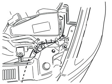
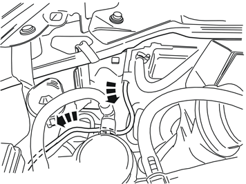
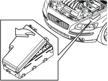
| | Cable routing and electrical connection: Route the cable with fuse and terminals up to the fuse box. Route the cable so that it is hidden and in such a way that it cannot be damaged.
|
|  | | J3703354 |
|
| | |
|  | | J3703355 |
|
| | |
|  | | J3703358 |
|
| | |
|  | | J3703359 |
|
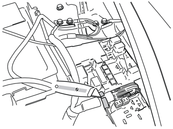
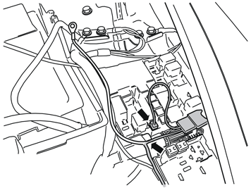
| | Pull in the fuse holder with fuse, as well as the red cable with cable terminal in the fuse box. Place the red cable in the cut-out in the rubber grommet and position the fuse holder with fuse on top of the existing cables as far to the left as possible in the fuse box. Connect the red cable to terminal 15 in the fuse box.
|
|  | | J3703356 |
|
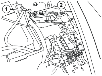
| | Take a cable tie from the kit and secure the fuse holder with fuse at the existing cables. Connect the pre-routed ground lead (1) to the exiting ground terminal (2). Tighten the ground screw. Tighten to 10Nm (7.5 lbf.ft.).
|
|  | | J3703357 |
|
| | |
|  | | J2900316 |
|
| | |
|  | | J2900458 |
|
| | |
|  | | J8504532 |
|
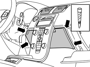
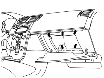
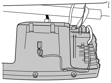
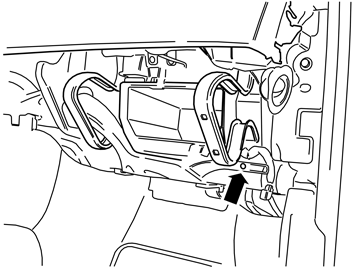
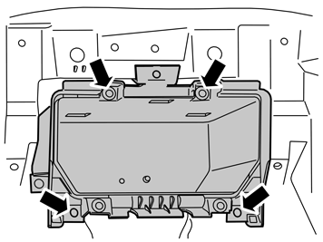
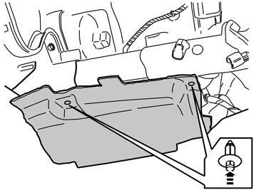
| | Open the glove compartment. Use a plastic weatherstrip tool to pry loose the panel. The panel is secured by two clips on each short side. Pull the panel away downwards.
|
|  | | J8903334 |
|
| | |
|  | | J8803118 |
|
| | |
|  | | J8803088 |
|
| | |
|  | | J8803119 |
|
| | |
|  | | J8803324 |
|
| | |
|  | | J8803325 |
|
| | |
|  | | J8504871 |
|
| | |
|  | | J3703360 |
|
| | |
|  | | J3703361 |
|
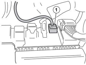
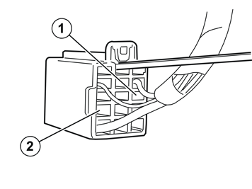
| | Move the catch holding the pin in the connector by pressing it to the side using a small screwdriver and pull the catch forward. Take the short cable harness from the kit. Connect the two pins of different sizes in the connector. Connect the green cable with the smaller pin in terminal 8 (1) and the black cable with larger pin in terminal 9 (2). The pins cannot be installed incorrectly as the pins are of different sizes. Press in the pins until they click into place. Press the catches that hold the pins back into place and reinstall the connector in the distribution box.
|
|  | | J3703362 |
|
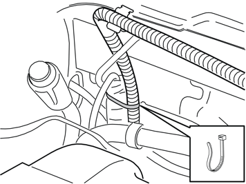
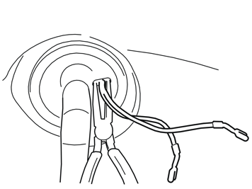
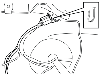
| | Fold the insulation mat to the side where it covers the rubber grommet. Make a hole in the rubber grommet using a pointed object at the side of the thick wiring in the middle. Use expansion pliers to enlarge the hole. Route a piece of wire or similar through the hole and out to the engine compartment. Secure the two cable ends at the wire using tape and route into the passenger compartment.
|
|  | | J3703363 |
|
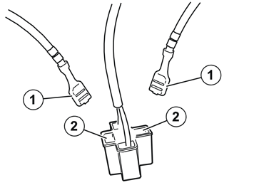
| | Pull the cable from the rubber grommet. Lubricate with normal soap if it is difficult to route through. Take the cable that has been routed into the passenger compartment. Connect the two flat pin connectors (1) to the available terminals (2) in the connector recently connected with the other cable.
Note!
The cables from the engine compartment can be connected in any of the two outer terminals. |
Take the relay from the kit and press into the connector.
|
|  | | J3703364 |
|
| | |
|  | | J8504532 |
|
| | |
|  | | J8504875 |
|
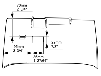
| | Mark out a rectangle on the panel, as illustrated, for installing the auxiliary lights switch. Drill four Ø 8mm (5/16") holes in the corners of the marked out rectangle. Saw/cut out the hole according to the markings. File or cut-out the corners so they become smooth. Smooth down the hole edges. Take the switch surround from the kit. Try pressing it into the hole. File to create more space if necessary.
|
|  | | J3904936 |
|
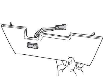
| | Take the switch from the kit and press it into the surround so that the hooks engage properly. Press the surround in the panel so that the hooks click into position. Reinstall the panel loosely to access the switch's connector.
|
|  | | J3703365 |
|
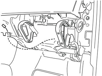
| | Route the wiring with the two-pin connector so that it is hidden under the panels and reaches the switch. Connect the connector to the switch's corresponding connector. Reinstall the panel completely.
|
| | |

