| | |
| | Read through all of the instructions before starting installation. Notifications and warning texts are for your safety and to minimise the risk of something breaking during installation. Ensure that all tools stated in the instructions are available before starting installation. Certain steps in the instructions are only presented in the form of images. Explanatory text is also given for more complicated steps. In the event of any problems with the instructions or the accessory, contact your local Volvo dealer.
|
| | |
|  | | IMG-400004 |
|
| | Caution!
Attach the antenna wires using tape. Cable ties or similar must not be used. |
Caution!
Make sure that the fiber optic cables are not bent to a radius of less than 25 mm. |
Note!
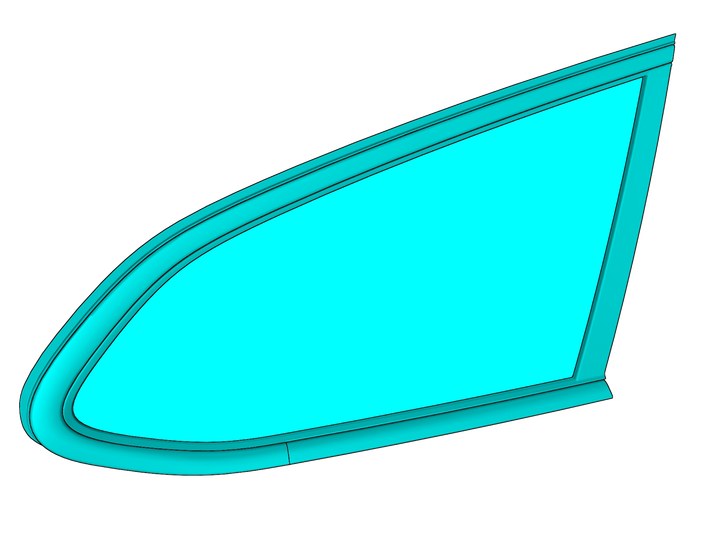
For vehicles without TV receiver, rear right side window needs to be replaced. |
|
| | |
|  | | IMG-400010 |
|
| | Note!
This colour chart displays (in colour print and electronic version) the importance of the different colours used in the images of the method steps. |
Used for focused component, the component with which you will do something. Used as extra colors when you need to show or differentiate additional parts. Used for attachments that are to be removed/installed. May be screws, clips, connectors, etc. Used when the component is not fully removed from the vehicle but only hung to the side. Used for standard tools and special tools. Used as background color for vehicle components. Used for accessory components.
|
| | |
|  | | IMG-342372 |
|
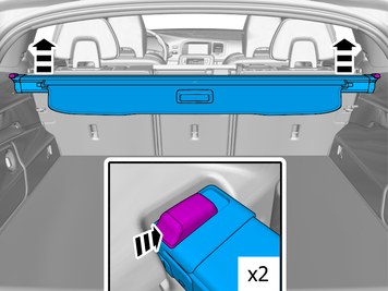
| | Repeat on the other side. |
|  | | IMG-360124 |
|
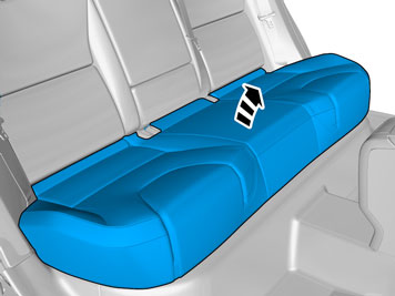
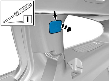
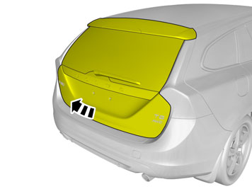
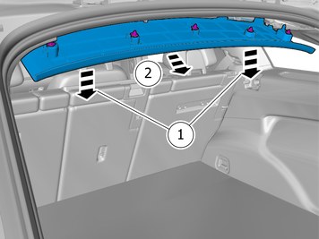
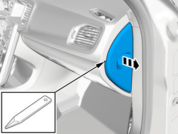
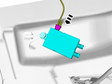
| | Remove the marked part. Disconnect any connector(s). |
|  | | IMG-344986 |
|
| | |
|  | | IMG-400820 |
|
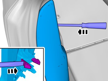
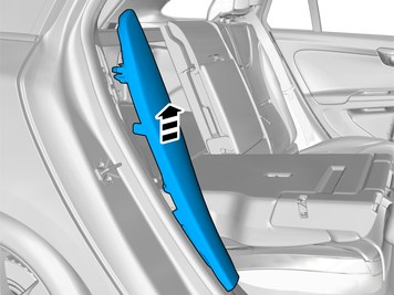
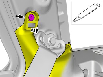
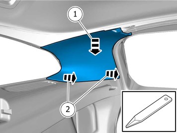
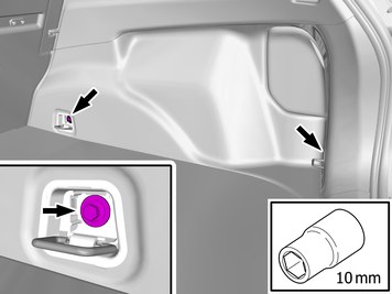
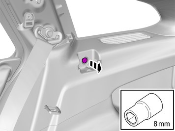
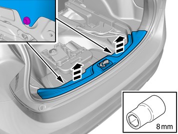
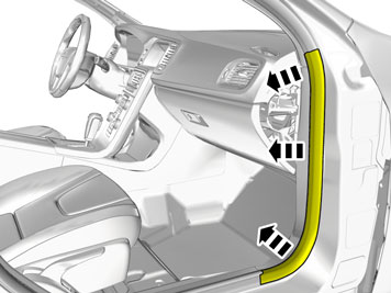
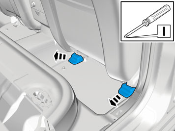
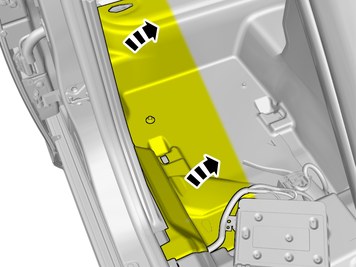
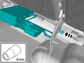
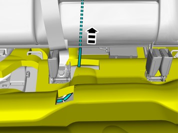
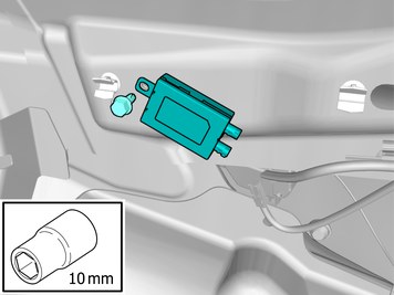
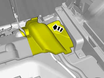
| | Loosen the marked detail. |
|  | | IMG-400821 |
|
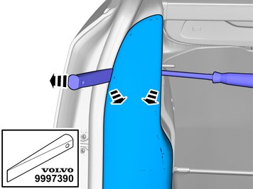
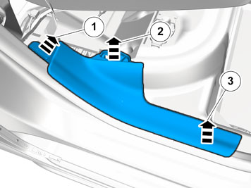
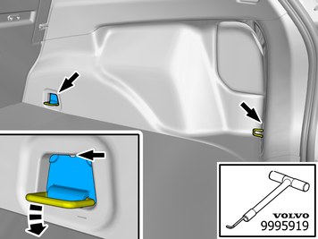
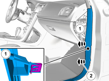
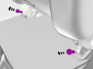
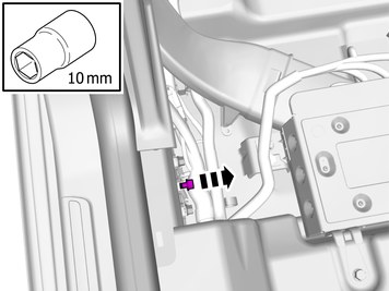
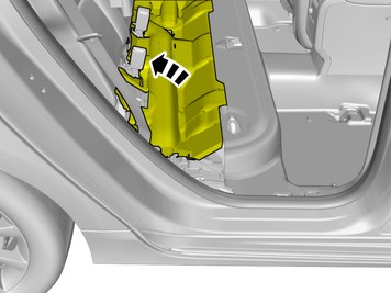
| | Loosen the marked detail. |
|  | | IMG-400822 |
|
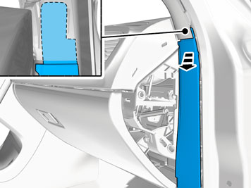
| | |
|  | | IMG-400815 |
|
| | |
|  | | IMG-400816 |
|
| | |
|  | | IMG-343417 |
|
| | |
|  | | IMG-461229 |
|
| | |
|  | | IMG-341906 |
|
| | |
|  | | IMG-461556 |
|
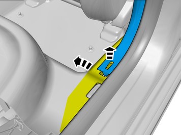
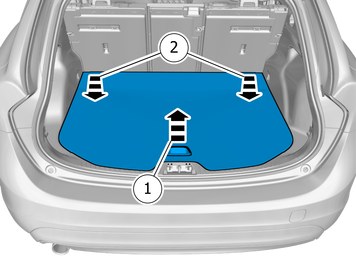
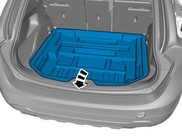
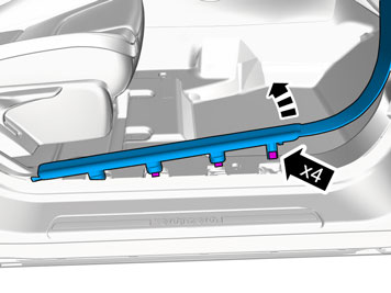
| | Detach the panel. Fold the carpet aside. |
|  | | IMG-351651 |
|
| | |
|  | | IMG-391390 |
|
| | |
|  | | IMG-461588 |
|
| | Note!
The clips consist of two parts. |
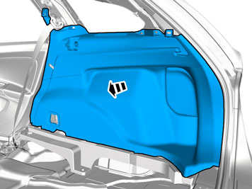
Remove the panel. Check that the fasteners are undamaged before installation. If not, they must be replaced with new ones. |
|  | | IMG-461286 |
|
| | |
|  | | IMG-461288 |
|
| | |
|  | | IMG-461289 |
|
| | |
|  | | IMG-461228 |
|
| | |
|  | | IMG-391570 |
|
| | |
|  | | IMG-342318 |
|
| | |
|  | | IMG-461558 |
|
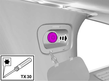
| | Remove the screws. Remove the panel. |
|  | | IMG-343425 |
|
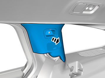
| | Remove the panel. Disconnect the connector. |
| | Vehicles with TV-receiver |
|  | | IMG-400000 |
|
| | Replace rear right side window according to VIDA service information. Information/ Repair/ Removal, replacement, installation/ 8 Body and interior/ 84 Exterior trim, glass, weatherstrips/ 844 glass for side doors and window/ Fixed side window |
|  | | IMG-462451 |
|
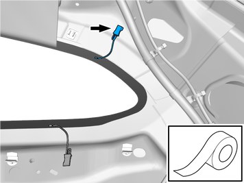
| | The connector is not to be used. Use tape |
| | |
|  | | IMG-344926 |
|
| | Remove the panel. Disconnect the connector, if applicable. |
|  | | IMG-344927 |
|
| | |
|  | | IMG-344928 |
|
| | Caution!
The front and upper sill panel must be removed and installed as one unit. |
|
|  | | IMG-344929 |
|
| | |
|  | | IMG-344930 |
|
| | |
|  | | IMG-340979 |
|
| | |
|  | | IMG-340980 |
|
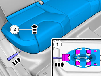
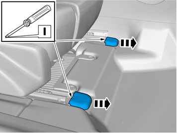
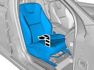
| | Remove the screws.
Tightening torque: Front seat to body
, 40 Nm
|
|  | | IMG-303005 |
|
| | |
|  | | IMG-303006 |
|
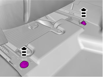
| | Remove the screws.
Tightening torque: Front seat to body
, 40 Nm
|
|  | | IMG-400002 |
|
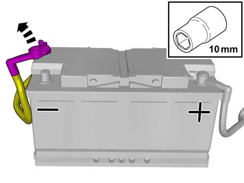
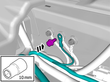
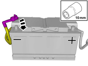
| | Remove the battery's negative cable. |
| | |
|  | | IMG-380657 |
|
| | |
| | |
|  | | IMG-380655 |
|
| | |
|  | | IMG-380656 |
|
| | |
| | |
|  | | IMG-329151 |
|
| | |
|  | | IMG-373198 |
|
| | |
|  | | IMG-329209 |
|
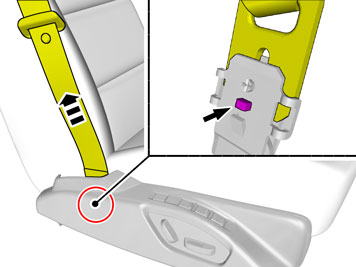
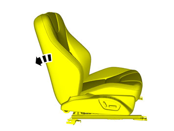
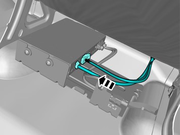
| | Loosen the screws. Disconnect the connector. |
|  | | IMG-382639 |
|
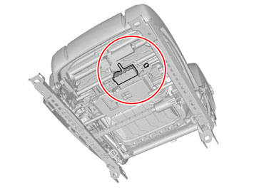
| | Disconnect the connector, if applicable. |
|  | | IMG-329153 |
|
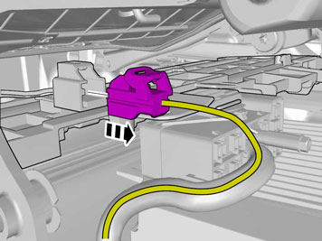
| | Caution!
Be extra careful when removing or installing this component. |
|
|  | | IMG-460418 |
|
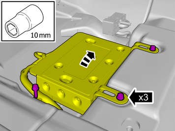
| | Remove the screws. Loosen the marked detail. |
| | Vehicles with High Performance Sound |
|  | | IMG-460425 |
|
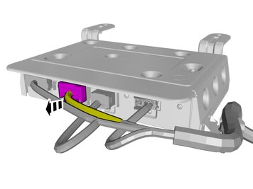
| | Disconnect the connector. |
| | Vehicles with Premium Sound |
|  | | IMG-460422 |
|
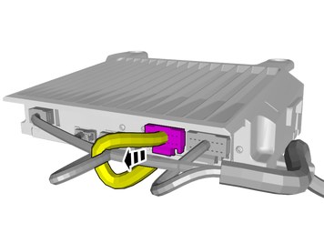
| | Disconnect the connector. |
| | |
|  | | IMG-460609 |
|
| | |
| | |
|  | | IMG-460610 |
|
| | Loosen the tape temporarily. The item is to be reused. |
|  | | IMG-460611 |
|
| | |
|  | | IMG-460426 |
|
| |
Use special tool: T9512620, Stripping tool (for wiring)
|
|  | | IMG-460764 |
|
| | Use detail according to image. |
|  | | IMG-460428 |
|
| |
Use special tool: T9512620, Stripping tool (for wiring)
|
|  | | IMG-460373 |
|
| | |
|  | | IMG-460547 |
|
| |
Use special tool: T9512785, Crimping tool (included in 9512669)
|
|  | | IMG-460375 |
|
| | Caution!
Make sure that the surrounding components are protected from heat. |
Use special tool: T9512777, Hot-air gun
|
|  | | IMG-460376 |
|
| | |
|  | | IMG-460660 |
|
| | |
|  | | IMG-460520 |
|
| | |
|  | | IMG-461499 |
|
| | |
|  | | IMG-461501 |
|
| | |
|  | | IMG-461502 |
|
| | Connect the ground cable. Reinstall the screw. |
|  | | IMG-461503 |
|
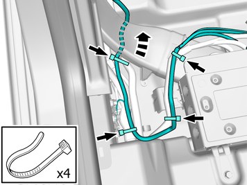
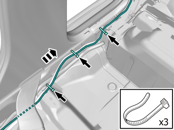
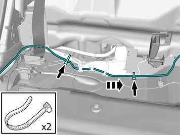
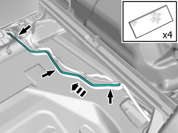
| | Route the cable harness to the existing cable harness. Install the wiring harness. Use a cable tie |
|  | | IMG-461506 |
|
| | Route the cable harness to the existing cable harness. Install the wiring harness. Use a cable tie |
|  | | IMG-461500 |
|
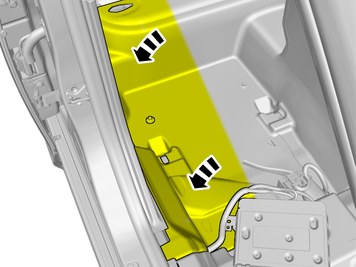
| | Fold the floor carpet back. |
|  | | IMG-460843 |
|
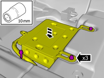
| | Caution!
Make sure that the fiber optic cables are not bent to a radius of less than 25 mm. |
Place the overlap of the cable mat under the amplifier. Reinstall the removed part. Reinstall the screws.
Tightening torque: M6
, 10 Nm
|
|  | | IMG-460480 |
|
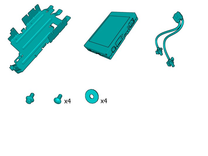
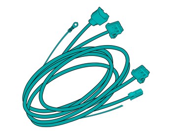
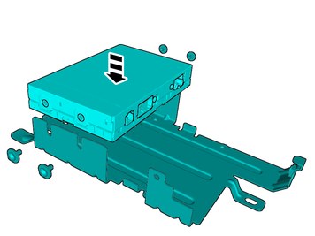
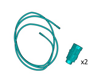
| | Assemble components that come with the accessory kit. |
|  | | IMG-460484 |
|
| | Install component that comes with the accessory kit. |
|  | | IMG-461563 |
|
| | |
|  | | IMG-461564 |
|
| | |
|  | | IMG-461565 |
|
| | |
|  | | IMG-461566 |
|
| | Install component that comes with the accessory kit. |
|  | | IMG-461567 |
|
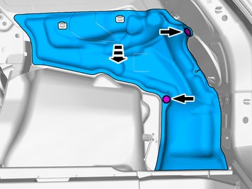
| | Fold the insulation aside. |
|  | | IMG-461509 |
|
| | Route the cable harness to the existing cable harness. Install the wiring harness. Use a cable tie |
|  | | IMG-461518 |
|
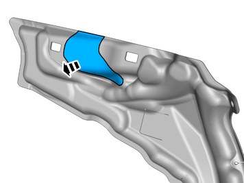
| | Pull the wiring harness through. Refit the insulation. |
|  | | IMG-461519 |
|
| | |
| | |
|  | | IMG-461422 |
|
| | Remove the clips. Remove the marked part. |
| | Vehicles with TV-receiver |
|  | | IMG-461521 |
|
| | |
| | Vehicles with TV-receiver |
|  | | IMG-461455 |
|
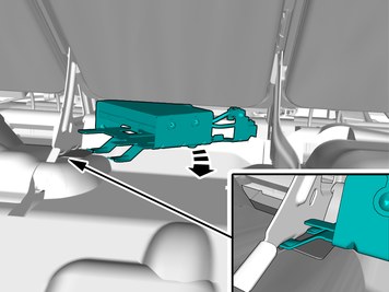
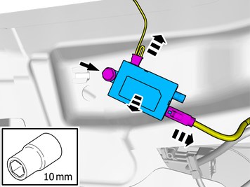
| | Disconnect the connectors. Remove the screw. Remove the marked part. |
| | |
| | |
|  | | IMG-461423 |
|
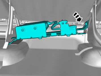
| | Install components that come with the accessory kit.
Tightening torque: M6
, 10 Nm
|
|  | | IMG-461434 |
|
| | |
|  | | IMG-460766 |
|
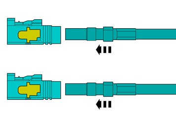
| | Use details according to image. |
|  | | IMG-460546 |
|
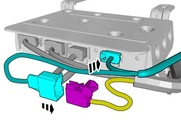
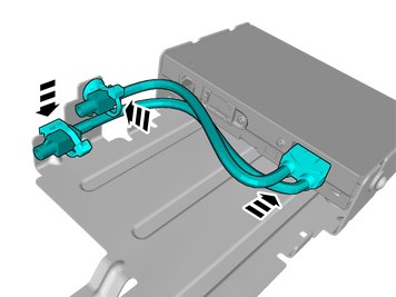
| | Assemble components that come with the accessory kit. Depress the secondary lock. |
| | Vehicles with TV-receiver |
|  | | IMG-461457 |
|
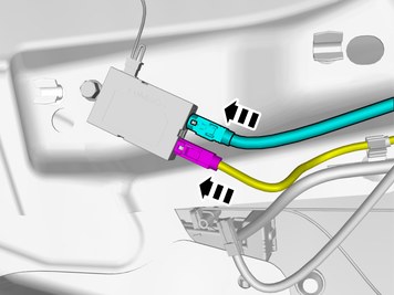
| | Connect the connector. Install component that comes with the accessory kit. |
| | Vehicles with TV-receiver |
|  | | IMG-461458 |
|
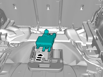
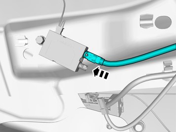
| | Install component that comes with the accessory kit. |
| | |
|  | | IMG-461425 |
|
| | Caution!
Attach the antenna wires using tape. Cable ties or similar must not be used. |
Route the wire adjacent to existing wirings. Install the cable. Use tape |
|  | | IMG-461150 |
|
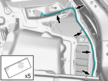
| | Route the wire adjacent to existing wirings. Install the cable. Use tape |
|  | | IMG-461524 |
|
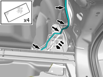
| | Fold the insulation aside. |
|  | | IMG-461152 |
|
| | Route the wire adjacent to existing wirings. Install the cable. Use tape |
|  | | IMG-461531 |
|
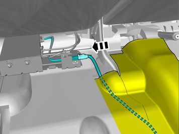
| | Pull the wiring harness through. Refit the insulation. Connect the connector. |
|  | | IMG-461534 |
|
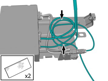
| | Caution!
Make sure that the fiber optic cables are not bent to a radius of less than 25 mm. |
Position the cable harness excess as illustrated. Install the wiring harness. Use tape |
| | Reinstall the removed parts in reverse order. |
|  | | IMG-400003 |
|
| | Reinstall the battery's negative cable. |
|  | | IMG-400006 |
|
| | Order and download software according to VIDA/SOFTWARE. Order and download software according to: 31268617
Download software (application) for the accessory's function according to the service information in VIDA. Order and download software according to: 31285168
|