| | |
|  | | IMG-363036 |
|
| | Color symbols Note!
This colour chart displays (in colour print and electronic version) the importance of the different colours used in the images of the method steps. |
Used for focused part, the part that you are to do something with. Used as extra colors when you need to show or differentiate additional parts. Used for attachments that are to be removed/installed. May be screws, clips, connectors, etc. Used when the component is not fully removed from the vehicle but only hung to the side. Used for standard tools and special tools. Used as background color for vehicle components.
|
|  | | IMG-330063 |
|
| | |
|  | | IMG-280223 |
|
| | |
|  | | IMG-231547 |
|
| | |
|  | | IMG-231549 |
|
| | |
|  | | IMG-231550 |
|
| | |
|  | | IMG-231551 |
|
| | |
|  | | IMG-231309 |
|
| | |
|  | | IMG-378244 |
|
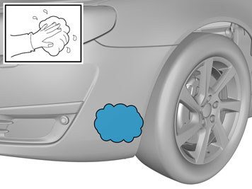
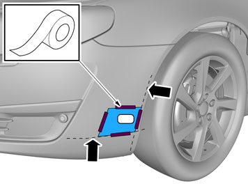
| | Clean where the template is to be attached |
|  | | IMG-378259 |
|
| | |
|  | | IMG-378251 |
|
| | |
|  | | IMG-378254 |
|
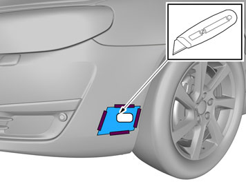
| | Note!
Cut carefully. It is easy to slip with the knife and move outside the template. |
Remove the template. Install the protective cover for the front engine block heater socket from the kit. Check that it aligns. Adjust the hole using a knife or file as necessary. Smooth off the hole edges. Remove any swarf.
|
|  | | IMG-231564 |
|
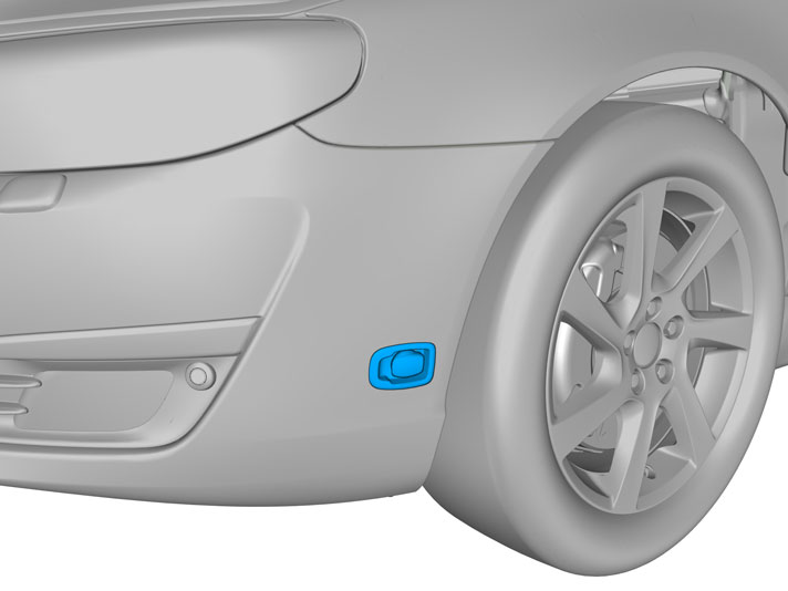
| | Press the protective cover (from the kit) into place in the hole cut in the bumper cover. Take the cable for the front engine block heater socket with ground lead from the kit and thread them through the protective cover.
|
|  | | IMG-231566 |
|
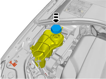
| | Install the attaching brace and nut from the kit. Plug the electrical connector into the front engine block heater socket. Use the connector as a counterhold when tightening. Tighten the front engine block heater socket to the bumper shell. Press the cable into the holder on the washer fluid reservoir. Remove the cover on the radiator expansion tank.
|
|  | | IMG-231565 |
|
| | |
|  | | IMG-231567 |
|
| | |
|  | | IMG-231568 |
|
| | |
|  | | IMG-231571 |
|
| | Drill a Ø4 mm (Ø5/32") hole for the front intake grounding on the underside of the left front side member as illustrated. Deburr the hole edges, remove the drill swarf and apply rustproofing agent. Take a screw and toothed washer from the kit. Tighten in the ground cable.
|
|  | | IMG-279168 |
|
| | |
|  | | IMG-213921 |
|
| | Note!
There is a large quantity of coolant in the system so position a receptacle under the engine. |
Pull out the plug and drain the coolant. Remove the sealing ring in the coolant pipe and check that it is intact. Replace if necessary. Lubricate the sealing ring with low temperature grease. Reinstall the sealing ring in the coolant pipe.
|
|  | | IMG-213922 |
|
| | Take the heater from the kit and press it into position on the coolant pipe, and lock it with the retaining clip. Check that the heater is fitted securely. Turn the heater so that it is clear of the surrounding components.
|
|  | | IMG-330833 |
|
| | |
|  | | R2900516 |
|
| | |
|  | | D3601932 |
|
| | Note!
Do not get any grease on the surfaces of the connector. |
|
|  | | IMG-330258 |
|
| | |
|  | | IMG-330259 |
|
| | Note!
Do not clamp the cables so that they make contact with pipes or hoses for the AC, brakes or power steering. |
|
|  | | IMG-330263 |
|
| | Route the cable from the engine block heater to the left toward the thick cable harness at the starter motor and up where the gearbox is connected to the engine. Route the cable to the front side of the engine/gearbox. Secure the wiring at the existing thick cable harness. Use the tie strap from the kit.
Note!
Do not clamp the cables so that they make contact with pipes or hoses for the AC, brakes or power steering. |
|
|  | | IMG-330273 |
|
| | Route the cable down from the gearbox mounting in the engine to the front side of the gearbox along the turbocharger pipe. Clamp the cable at the thick cable harness on the right hand side of the air cleaner with a tie strap.
|
|  | | IMG-330274 |
|
| | |
|  | | IMG-214134 |
|
| | |
|  | | IMG-330275 |
|
| | Take the two clips from the kit. Press them onto the subframe's upper/front edge and at the left front-edge of it, according to the dimensions in the illustration. If the passenger compartment switch is installed at the same time, the position of the right hand clip must be adapted to the junction connector that is supplied.
|
| | | D3601932 |
|
| | Note!
Do not get any grease on the surfaces of the connector. |
|
|  | | IMG-330278 |
|
| | Applies when only the engine block heater is installed |
|  | | IMG-330279 |
|
| | Pres the cable from the front intake in the two clips in the upper edge of the sub-frame and clamp the cable joint on the inside of the sub-frame using the tie-strap. Clamp the cable at the stay for the engine cooling fan using the tie strap and in the upper corner of the sub frame with the clip tie strap. Ensure that clamp's clip is positioned so that the cable is fixed against this and does not rub against the sub-frame.
|
|  | | IMG-330280 |
|
| | Applies when fitting passenger compartment connector at the same time |
|  | | IMG-330281 |
|
| | Insert the junction connector in the space in the subframe. Secure the junction connector by fastening the cable tie through the rear hole of the connector. Install the cable in the other clamps in the same way as in point B.
|
|  | | IMG-231579 |
|
| | Applies to all vehicles Installation |
|  | | IMG-279192 |
|
| | |
|  | | IMG-279193 |
|
| | |
|  | | J2600418 |
|
| | |
|  | | J2600419 |
|
| | |
|  | | J2600420 |
|
| | |
|  | | IMG-280243 |
|
| | |
|  | | IMG-231335 |
|
| | |
|  | | IMG-317784 |
|
| | |