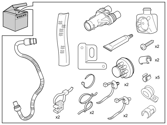
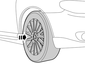
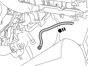
| | Note!
Some steps in these installation instructions are presented with illustration only. |
|
|  | | IMG-245980 |
|
| | |
|  | | IMG-217765 |
|
| | |
|  | | IMG-217766 |
|
| | |
|  | | IMG-217767 |
|
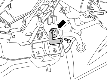
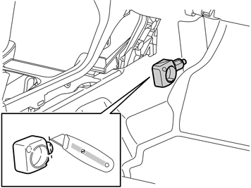
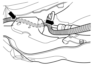
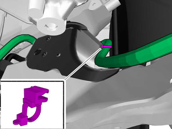
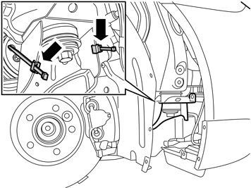
| | Undo the front screw in the mounting for the centre console. Take the bracket for the passenger compartment connector from the kit and tighten it in with the previously removed screw. Align the bracket so that it is straight and torque tighten the screw to 24 Nm (18 lbf.ft.).
|
|  | | IMG-217768 |
|
| | |
|  | | IMG-217769 |
|
| | |
|  | | IMG-217770 |
|
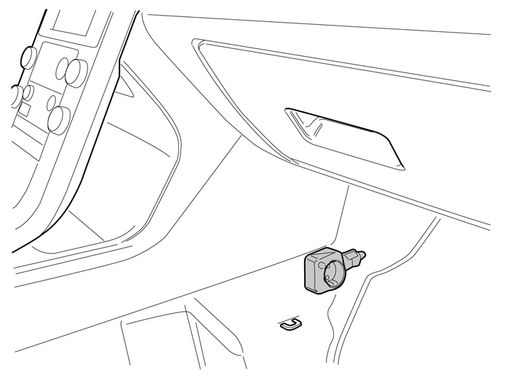
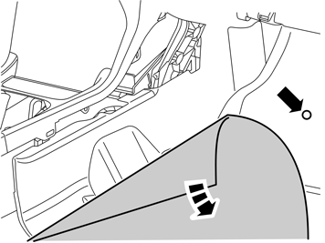
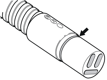
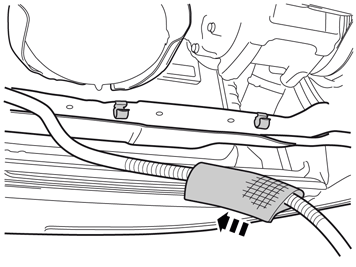
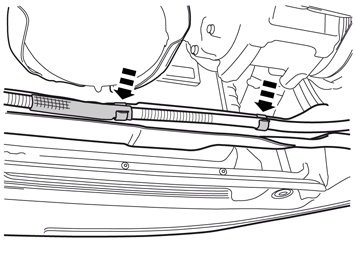
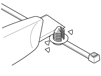
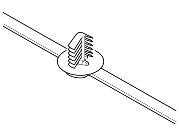
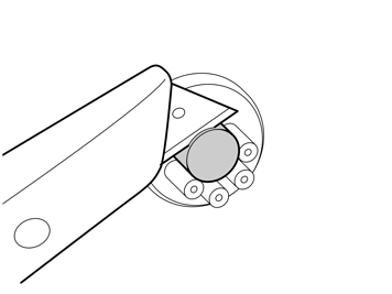
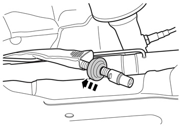
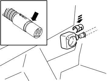
| | Press a locking sleeve (from the kit) onto the passenger compartment connector socket. Slide the locking sleeve as far along the terminal for the passenger compartment connector socket as possible. Take a carpet knife and cut a slit in the carpet just in front of the locking sleeve. Make the cut as long as the diameter of the locking sleeve.
Note!
Do not damage any wiring and hoses under the carpet. |
Remove the passenger compartment connector socket from the bracket and fold the carpet to one side.
|
|  | | IMG-217771 |
|
| | |
|  | | IMG-217772 |
|
| | |
|  | | IMG-217773 |
|
| | |
|  | | IMG-231820 |
|
| | |
|  | | IMG-231309 |
|
| | |
|  | | IMG-231821 |
|
| | |
|  | | IMG-330308 |
|
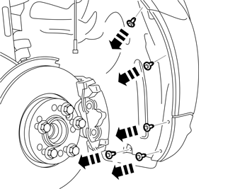
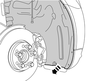
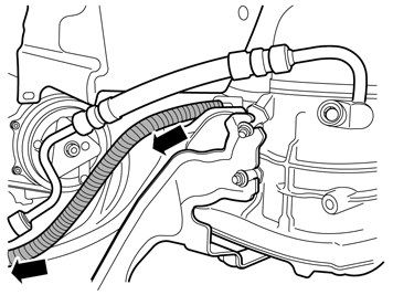
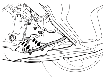
| | Clamping for 4-cyl. diesel engine shown Remove the cable to the engine heater from the three tie straps and the panel clip in the bracket for the cooling fan and the subframe.
|
|  | | IMG-330309 |
|
| | |
|  | | IMG-330310 |
|
| | |
|  | | IMG-330311 |
|
| | |
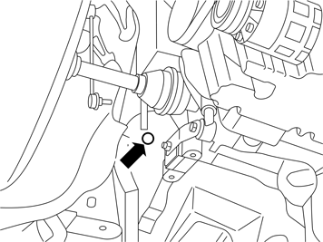
|  | | D3601932 |
|
| | Note!
Do not get any grease on the surfaces of the connector. |
|
|  | | IMG-330313 |
|
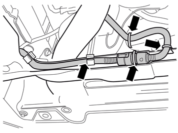
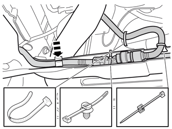
| | Connect: cable (1) from the front engine block heater socket cable (2) to the passenger compartment connector socket cable (3) to the heater. Take three locking sleeves from the kit and install them over the joints.
|
|  | | IMG-330314 |
|
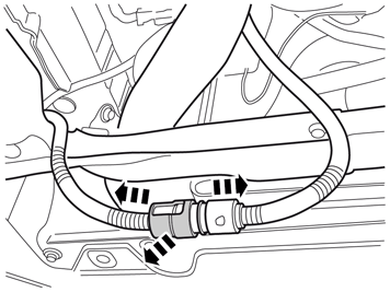
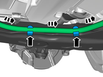
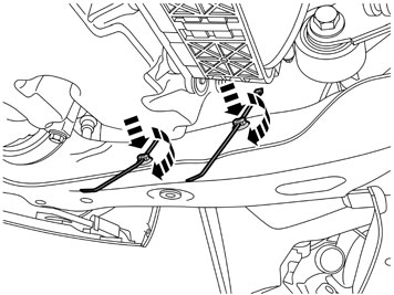
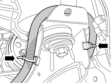
| | Clamping for 4-cyl. diesel engine D4164 shown Insert the junction connector in the space in the subframe. Secure the junction connector by fastening the cable tie through the rear hole of the connector. Install new cable tie in the clip in the upper edge of the sub frame instead of the one that was cut off. Install the cable in the bracket for the cooling fan using the cable tie. Tighten this clamp so that the cable rests against the clip and does not rub against the sub-frame. Press the cable into the panel clip. This may need to be moved.
Note!
On other engine types the branching connector may have to be clamped down around the rear of the contacts for the cable to the engine heater to be routed correctly. |
|
|  | | IMG-330315 |
|
| | Only applies to cars with 4-cyl. diesel engine D4164 |
|  | | IMG-330316 |
|
| | Only applies to cars with 4-cyl. diesel engine D4164 |
|  | | IMG-330317 |
|
| | Applies to all models Only applies to cars with 4-cyl. diesel engine D4164 The left clip should also hold the heat guard.
|
|  | | IMG-330318 |
|
|  | | IMG-330319 |
|
| | Applies to cars with EHPAS Illustrations A and B |
|  | | IMG-359903 |
|
| | |
|  | | IMG-359904 |
|
| | |
|  | | IMG-359905 |
|
|  | | IMG-359906 |
|
| | |
|  | | IMG-214133 |
|
| | Applies to cars without EHPAS |
|  | | IMG-332957 |
|
|  | | IMG-332958 |
|
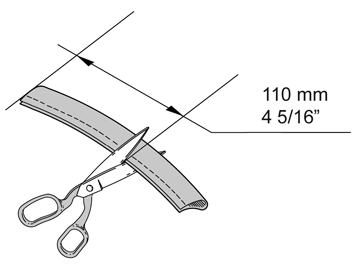
| | Illustrations A and B Note!
On certain cars the two holes in the subframe's right side, used for clamping of the passenger compartment connector's cable, are provided with rivet nuts. For the clips in the kit to fit they must be cut as shown. |
|
|  | | IMG-332959 |
|
|  | | IMG-214140 |
|
| | Illustration A Applies to cars with rivet nuts in the clip holes Screw the clips into the rivet nuts.
Illustration B Applies to cars without rivet nuts in the clip holes Press the clips into the clips holes.
|
| | | IMG-359905 |
|
| | | IMG-359906 |
|
| | |
|  | | IMG-214132 |
|
|  | | IMG-277511 |
|
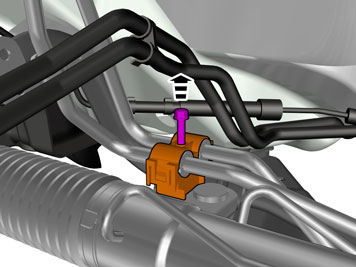
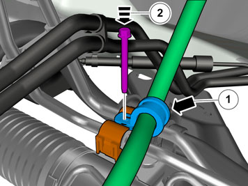
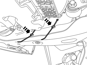
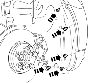
| | Illustration A Note!
Do not clamp the cable directly to brake pipes, fuel lines, power steering pipes or AC pipes. |
Illustration B |
|  | | IMG-231839 |
|
| | |
|  | | IMG-277513 |
|
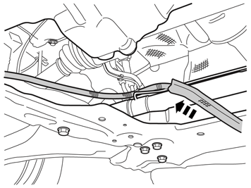
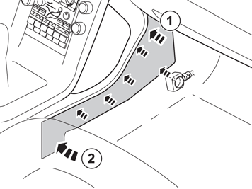
| | Adjust the length of the cable from place where the rubber grommet should be located and out into the engine compartment so that it runs true and does not come into contact with any moving parts in the engine compartment. Conceal all cable excess under the mat in the passenger compartment. The radiation shield may need to be cut to fit the length of the cable between the clamp and the rubber lead-in in the firewall. Take the radiation shield from the kit and thread it on the cable to the passenger compartment connector. Pull the radiation shield onto the cable clamp.
|
|  | | IMG-277514 |
|
| | |
|  | | IMG-277515 |
|
| | |
|  | | IMG-277516 |
|
| | |
|  | | IMG-231335 |
|
| | |
|  | | IMG-217778 |
|
| | |
|  | | IMG-231842 |
|
| | |
|  | | IMG-231843 |
|
| | |
|  | | IMG-231844 |
|
| | |
|  | | IMG-217776 |
|
|  | | IMG-217777 |
|
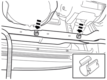
| | Illustration A Illustration B Route the cable from the engine compartment through the hole in the carpet. Lubricate the O-ring using low temperature grease.
Note!
Ensure that no grease gets onto the connector surfaces. |
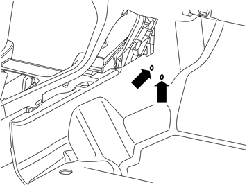
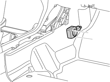
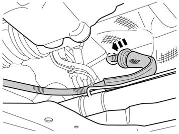
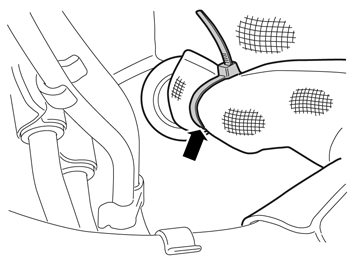
Connect the cable to the passenger compartment connector socket. Press a locking sleeve (from the kit) over the joint. Fold the carpet back into position and install the passenger compartment connector socket using both the screws.
|
|  | | IMG-234260 |
|
| | |