| | |
| | Read through all of the instructions before starting installation. Notifications and warning texts are for your safety and to minimise the risk of something breaking during installation. Ensure that all tools stated in the instructions are available before starting installation. Certain steps in the instructions are only presented in the form of images. Explanatory text is also given for more complicated steps. In the event of any problems with the instructions or the accessory, contact your local Volvo dealer.
|
| | |
|  | | IMG-363036 |
|
| | Note!
This colour chart displays (in colour print and electronic version) the importance of the different colours used in the images of the method steps. |
Used for focused component, the component with which you will do something. Used as extra colors when you need to show or differentiate additional parts. Used for attachments that are to be removed/installed. May be screws, clips, connectors, etc. Used when the component is not fully removed from the vehicle but only hung to the side. Used for standard tools and special tools. Used as background color for vehicle components.
|
| | |
|  | | IMG-335491 |
|
| | |
| | |
|  | | IMG-273525 |
|
| | |
|  | | IMG-273526 |
|
| | |
|  | | IMG-268004 |
|
| | |
|  | | IMG-268005 |
|
| | |
|  | | IMG-268007 |
|
| | |
|  | | IMG-268009 |
|
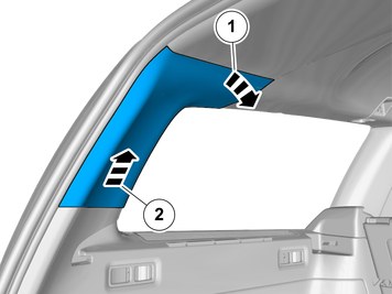
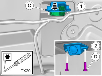
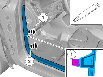
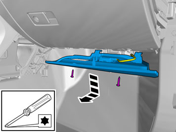
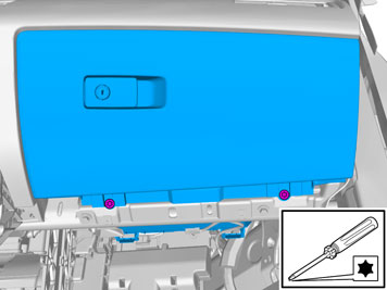
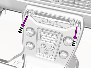
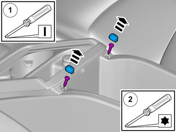
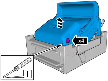
| | Remove the screw. Detach the panel. Repeat on the other side. |
|  | | IMG-268011 |
|
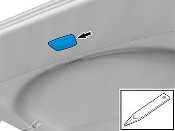
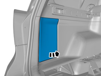
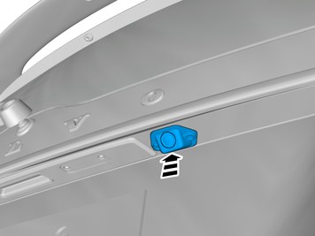
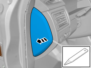
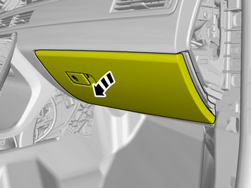
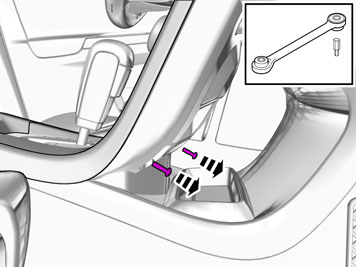
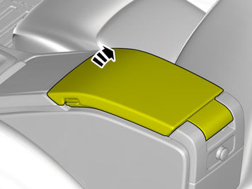
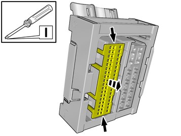
| | Remove the part carefully |
|  | | IMG-268010 |
|
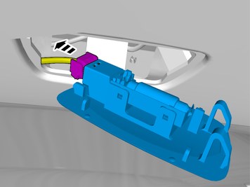
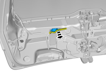
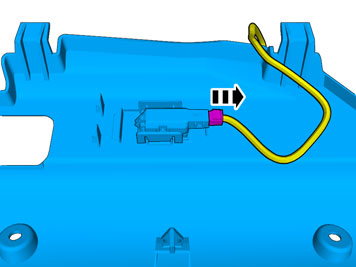
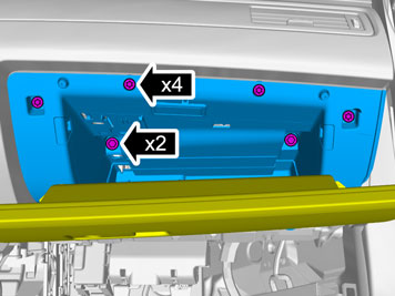
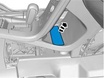
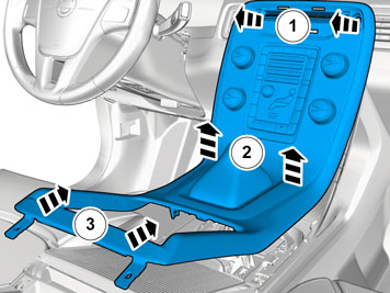
| | Remove the part carefully Disconnect the connector, if applicable. |
|  | | IMG-392004 |
|
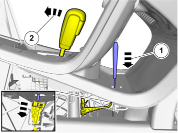
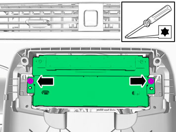
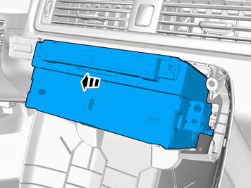
| | Caution!
Check that the component does not show deformation damage. |
Note!
The marked component is a spare part and can be replaced with a new if necessary. |
|
|  | | IMG-392050 |
|
| | Caution!
Check that the component does not show deformation damage. |
Note!
The marked component is a spare part and can be replaced with a new if necessary. |
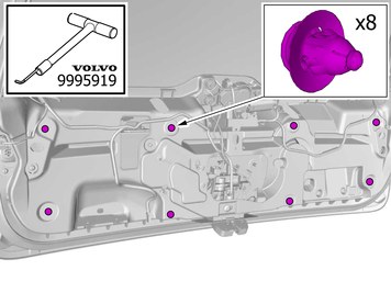
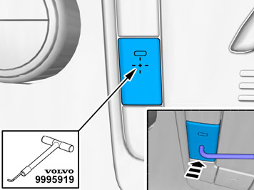
Use special tool: T9995919, PULLER (SEAL-PINION,CAM-CRANKSHAFT)B200-6304
|
|  | | IMG-402015 |
|
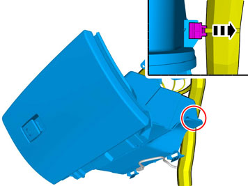
| | Remove the part carefully |
|  | | IMG-402022 |
|
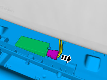
| | Disconnect the connector. |
|  | | IMG-402021 |
|
| | |
|  | | IMG-350221 |
|
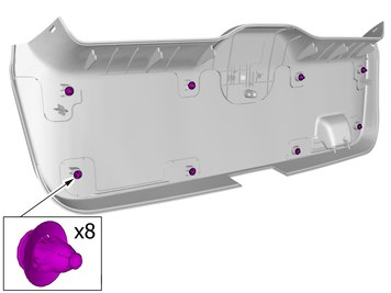
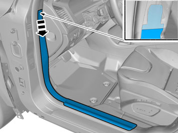
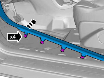
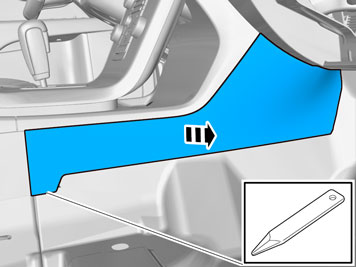
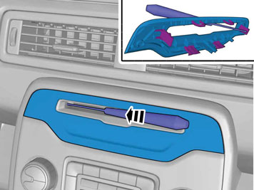
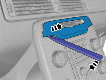
| | Remove the panel. Check that the fasteners are undamaged before installation. If not, they must be replaced with new ones. |
|  | | IMG-401980 |
|
| | |
|  | | IMG-399272 |
|
| | |
|  | | IMG-259759 |
|
| | |
|  | | IMG-268016 |
|
| | Remove the panel. Check that the fasteners are undamaged before installation. If not, they must be replaced with new ones. |
| | |
|  | | IMG-402036 |
|
| | |
|  | | IMG-402035 |
|
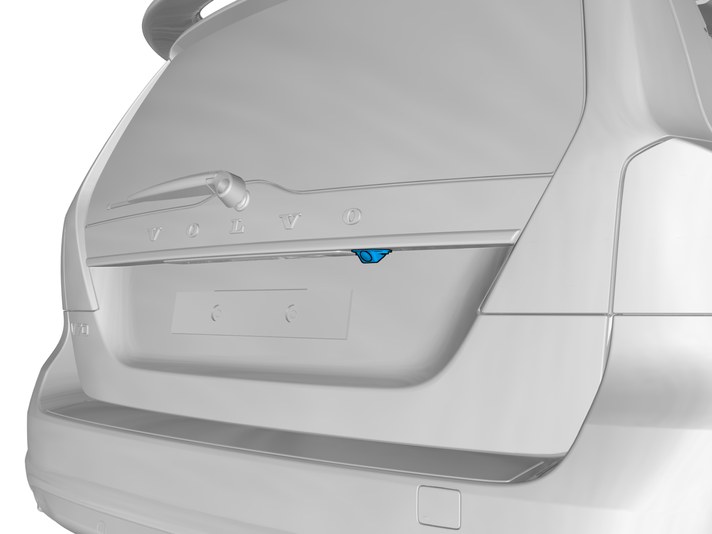
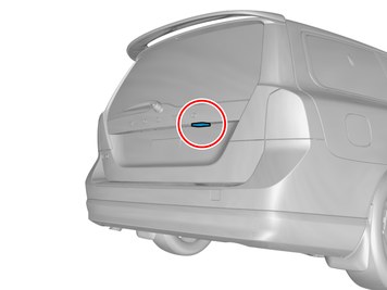
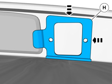
| | Place the component where indicated in the graphic. Scribe/mark up |
|  | | IMG-402051 |
|
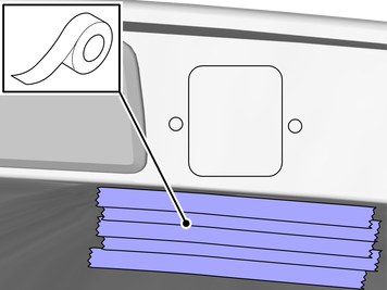
| | Caution!
Make sure to protect adjacent surfaces or components. |
Use tape |
|  | | IMG-402046 |
|
| | |
|  | | IMG-402048 |
|
| | |
|  | | IMG-389402 |
|
| | |
|  | | IMG-389380 |
|
| | |
|  | | IMG-389429 |
|
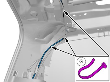
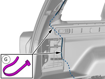
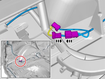
| | Loosen the wiring harness or move it to the side. |
|  | | IMG-389794 |
|
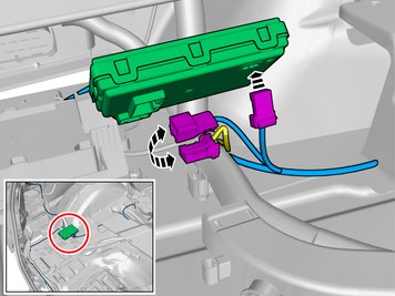
| | Install component that comes with the accessory kit. Install the screws.
|
|  | | IMG-402001 |
|
| | Repeat on the other side. |
|  | | IMG-401994 |
|
| | Repeat on the other side. |
|  | | IMG-402055 |
|
| | Tape the cables on the cable tie. Use: , Electrical tape
|
|  | | IMG-402056 |
|
| | |
|  | | IMG-389588 |
|
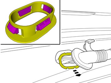
| | Caution!
Ensure that the wire or wiring harness cannot rub against adjacent components. |
Pull the wiring through. Remove the cable tie(s). |
|  | | IMG-401912 |
|
| | |
|  | | IMG-399835 |
|
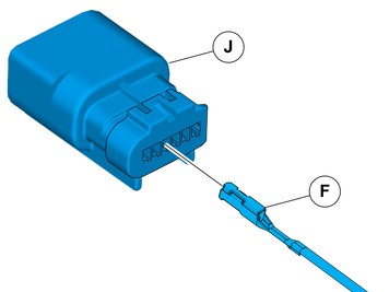
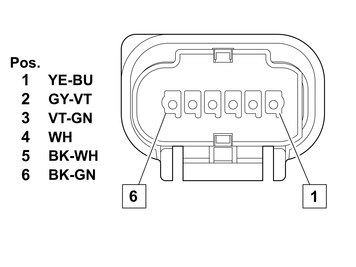
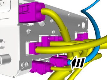
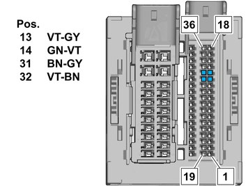
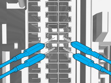
| | Connect the cable harness terminals in the connector as follows. |
|  | | IMG-401095 |
|
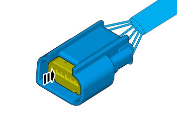
| | Depress the secondary lock. |
|  | | IMG-389796 |
|
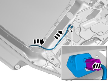
| | Connect the connector. Clamp the cables and connectors to the existing cables to prevent noise. |
| | |
|  | | IMG-402060 |
|
| | |
|  | | IMG-402075 |
|
| | |
|  | | IMG-402070 |
|
| | |
| | |
|  | | IMG-399270 |
|
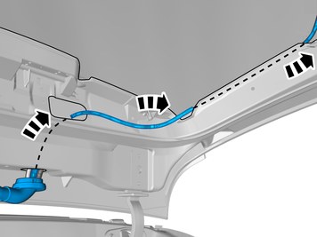
| | Caution!
Ensure that the wire or wiring harness cannot rub against adjacent components. |
Route the wire adjacent to existing wirings. Install the cable. Use a cable tie |
|  | | IMG-399271 |
|
| | Caution!
Ensure that the wire or wiring harness cannot rub against adjacent components. |
Route the wire adjacent to existing wirings. Use a cable tie Install the cable. |
|  | | IMG-353734 |
|
| | |
|  | | IMG-353736 |
|
| | |
| | |
|  | | IMG-391287 |
|
| | Connect the cable harness. Clamp the cables and connectors to the existing cables to prevent noise. |
| | Vehicles without tow hitch. |
|  | | IMG-391291 |
|
| | Connect the cable harness. Clamp the cables and connectors to the existing cables to prevent noise. |
| | |
| | |
|  | | IMG-346689 |
|
| | |
|  | | IMG-338119 |
|
| | |
|  | | IMG-346676 |
|
| | Caution!
The front and upper sill panel must be removed and installed as one unit. |
|
|  | | IMG-346681 |
|
| | |
|  | | IMG-346677 |
|
| | |
|  | | IMG-346682 |
|
| | |
| | Vehicles with integrated child safety seat |
|  | | IMG-319024 |
|
| | |
|  | | IMG-319025 |
|
| | |
| | |
|  | | IMG-402030 |
|
| | Remove the marked part. Check that the fasteners are undamaged before installation. If not, they must be replaced with new ones. |
|  | | IMG-402031 |
|
| | |
|  | | IMG-402025 |
|
| | |
|  | | IMG-347139 |
|
| | Remove the panel. When removing on right-hand drive cars, perform the procedures on the opposite side and/or mirrored. |
|  | | IMG-355521 |
|
| | Remove the screws. Detach the panel. |
|  | | IMG-355519 |
|
| | Disconnect the connector. Remove the panel. |
|  | | IMG-354313 |
|
| | Remove the panel. Disconnect the connector, if applicable. |
|  | | IMG-357381 |
|
| | |
|  | | IMG-373498 |
|
| | |
|  | | IMG-357380 |
|
| | Remove the screws. Note the position. |
|  | | IMG-373518 |
|
| | |
|  | | IMG-356889 |
|
| | Disconnect the connector. |
|  | | IMG-357382 |
|
| | Unhook the cable harness clips. |
| | | IMG-373518 |
|
| | |
|  | | IMG-354292 |
|
| | |
|  | | IMG-354291 |
|
| | |
|  | | IMG-349806 |
|
| | |
|  | | IMG-345282 |
|
| | |
| | Cars with automatic transmissions |
|  | | IMG-293006 |
|
| | |
|  | | IMG-293007 |
|
| | |
| | |
|  | | IMG-353601 |
|
| | |
|  | | IMG-353602 |
|
| | |
|  | | IMG-349826 |
|
| | Caution!
Be careful not to damage the catches. |
Detach the panel. |
|  | | IMG-349942 |
|
| | |
|  | | IMG-349946 |
|
| | |
| | |
| | |
|  | | IMG-390146 |
|
| | Caution!
Ensure that the wire or wiring harness cannot rub against adjacent components. |
Position/route the cable harness as illustrated. |
|  | | IMG-390151 |
|
| | Caution!
Ensure that the wire or wiring harness cannot rub against adjacent components. |
Route the wire adjacent to existing wirings. |
| | Right-hand drive vehicles |
|  | | IMG-390263 |
|
| | Caution!
Ensure that the wire or wiring harness cannot rub against adjacent components. |
Route the cable harness to the existing cable harness. Clamp the cables and connectors to the existing cables to prevent noise. |
| | |
|  | | IMG-384929 |
|
| | Connect the prerouted cable. |
|  | | IMG-349948 |
|
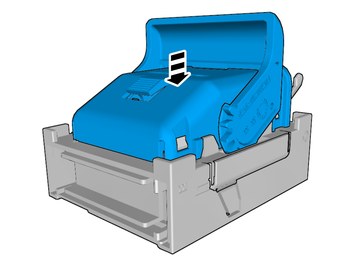
| | Reinstall the removed part. |
|  | | IMG-390597 |
|
| | Caution!
Ensure that the wire or wiring harness cannot rub against adjacent components. |
When installing on right-hand drive cars, perform the procedures on the opposite side and/or mirrored. Fold the carpet aside. Pull the wiring through. Route the cable harness to the existing cable harness. Clamp the cables and connectors to the existing cables to prevent noise. |
|  | | IMG-401933 |
|
| | |
|  | | IMG-400319 |
|
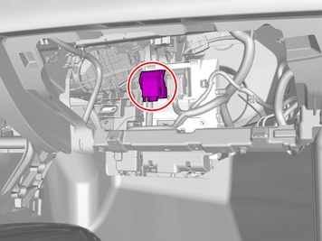
| | Depress the locking device. Release the connector's catch. Disconnect the connector. |
|  | | IMG-387423 |
|
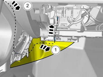
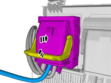
| | Release the catches. Remove the marked part. |
|  | | IMG-400415 |
|
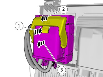
| | Release the connector's secondary lock. Lift approximately 2 mm. |
|  | | IMG-401921 |
|
| | Connect the cable harness terminals in the connector as follows. |
|  | | IMG-400381 |
|
| | |
|  | | IMG-387424 |
|
| | Reinstall the removed parts in reverse order. Reinstall the removed part. |
|  | | IMG-400420 |
|
| | |
|  | | IMG-400000 |
|
| | Reinstall the removed parts in reverse order. |
| | |
|  | | IMG-382371 |
|
| | |
|  | | IMG-381005 |
|
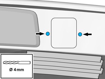
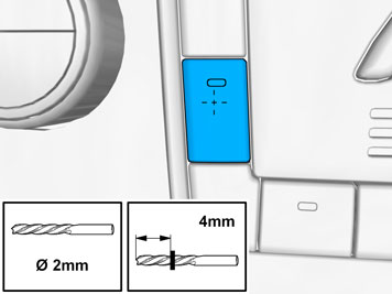
| | Measure and mark as illustrated. |
|  | | IMG-381006 |
|
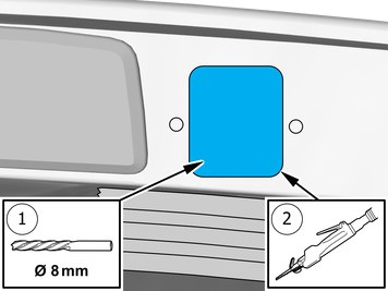
| | Use a drill with the stated size |
|  | | IMG-381020 |
|
| |
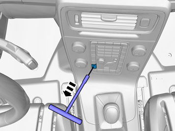
Use special tool: T9995919, PULLER (SEAL-PINION,CAM-CRANKSHAFT)B200-6304
|
|  | | IMG-380996 |
|
| | |
| | |
|  | | IMG-382374 |
|
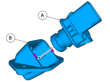
| | Install component that comes with the accessory kit. |
| | |
|  | | IMG-377070 |
|
| | Reinstall the removed parts in reverse order. |
|  | | IMG-336901 |
|
| | |
|  | | IMG-336904 |
|
| | Warning!
When switching the ignition on for the first time after a battery disconnect and connect, make sure to stand outside the vehicle and only reach into the vehicle keeping clear of the air bag deployment areas. |
|
|  | | IMG-242268 |
|
| | Download software (application) for the accessory's function according to the service information in VIDA. Order and download software according to: 31428822
|
|  | | IMG-354602 |
|
| | Warning!
Check for correct operation after the installation. |
|